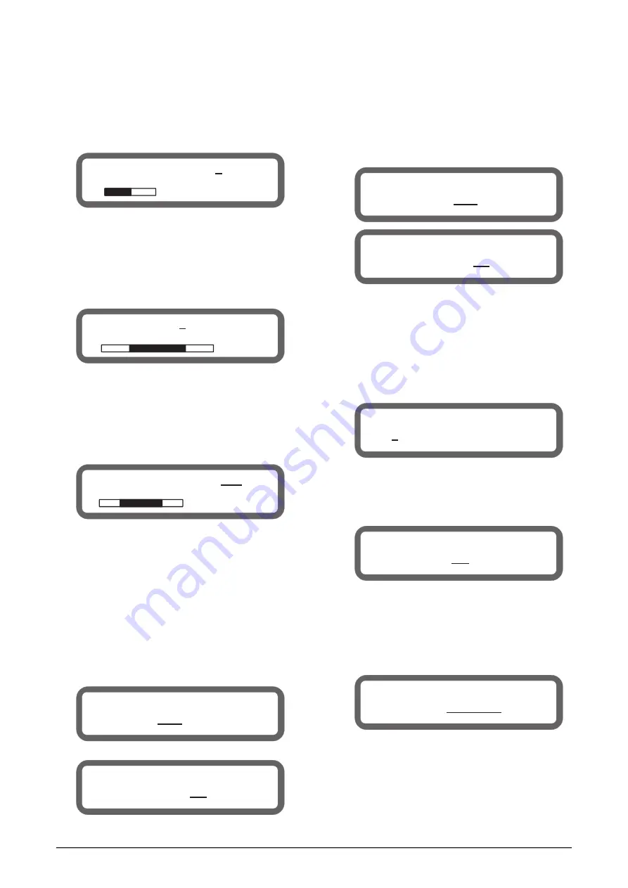
933.35mS
321.47m
2241.21ft
2 IN-A DELAY:
ON
4 IN-A COMPRESS
OFF
+3.5dBu
4:1 AT: 25mS
RT: 200mS
5 IN-A CHANNEL LINK
Link to IN-D: OFF
5 IN-A CHANNEL LINK
Are you sure ? NO
4 OUT1 HIGH_PASS_FILTER
1620Hz 12 dB Linkriley
2 OUT1
SET PHASE
Phase: 180
°
7 OUT1 SET SOURCE
Source: IN-A+IN-B
6 IN-A
CHANNEL COPY
COPY TO:
IN-B
6 IN-A
Copy data to IN-B
Are you sure ?
NO
3.2.3 Input / Output Delay Set
®
Press MAIN MENU
or
to switch to DELAY settings page.
®
Rotate the Rotary Encoder to change the parameters with the
step of 0.021ms.
◀
▶
®
3.2.4 Input / Output PEQ Set
®
Press MAIN MENU
◀
or
▶
to switch to PEQ settings page.
®
Press CURSOR
◀
or
▶
to move the cursor position.
®
Rotate the Rotary Encoder to adjust the parameters at the
cursor position.
®
The Frequency, Gain of PEQ can be adjusted coarse or fine at
the cursor position.
3.2.5 Input / Output Compressor Set
®
Press MAIN MENU
◀
or
▶
to switch to COMPRESS settings
page.
®
Press CURSOR
◀
or
▶
to move the cursor position.
®
Rotate the Rotary Encoder to adjust the parameters at the cursor
position.
3.2.6 Input / Output LINK Set
®
Press MAIN MENU
◀
or
▶
to switch to LINK settings page.
®
Press CURSOR
◀
or
▶
to move the Cursor position.
®
Rotate the Rotary Encoder to adjust the parameters at the cursor
position.
®
Press SAVE/ENTER into the link confirmation dialogs.
®
Default is NO, no link setting. Switch between YES and NO
with the Rotary Encoder.
Pr
®
ess SAVE/ENTER again to confirm the link setting.
Note:
If
Yes is chosen as link set, the source channel parameters
will
be copied to the target channel.
Can also press CURSOR
◀
or
▶
to change the cursor's
position below the value, in order to switch to other step, such
as 105ms, 10.5ms, 1.05ms, 0.105ms, 0.021ms, or adjust the
Delay switch.
3.2.7 Data COPY of Input / Output Channel
®
Press MAIN MENU
to switch to COPY settings page.
®
Rotate the Rotary Encoder to change the target channel.
®
Press SAVE / ENTER into COPY confirmation dialogs.
®
Default is NO, no copy operation. Switch between YES and NO
with the Rotary Encoder.
®
Press SAVE / ENTER again to confirm the copy operation.
Note: At the COPY set, the source channel parameters will be
copied to the target channel.
3.2.8 Output HIGH/LOW PASS FILTER Set
®
Press MAIN MENU
to switch to HIGH/LOW - PASS
Filter settings page.
®
Press CURSOR
to move the cursor.
®
Rotate the Rotary Encoder to adjust the parameters at the cursor
position.
The frequency of
ilter can be adjusted
coarse or fine at the cursor position.
3.2.9 Output PHASE Set
®
Press MAIN MENU
to switch to PHASE settings page.
®
Rotate the Rotary Encoder to change PHASE parameter.
3.2.10 SOURCE Set
®
Press MAIN MENU
to switch to SOURCE settings
page.
Rotate the
Encoder to change SOURCE parameter.
◀
or
▶
◀
or
▶
◀
or
▶
®
HIGH/LOW - PASS F
◀
or
▶
◀
or
▶
®
Rotary
3 IN-A PEQ 1 ON
PEQ
31.3Hz +0.0dB 0.500
A11: ON
6


