- 11 -
ADJUSTMENT INSTRUCTIONS
8. Sub-Tint Adjustment
Sub-Tint adjustment doesn’t need to be adjusted in Line
process but it is display in adjustment mode to correspond
with SVC.
9. Deflection Adjustment
9.1 Preliminary Steps
(1) Set the Deflection data with the SVC Remote control.
(2) Enter into Deflection adjustment mode by pressing the
INSTART button and select CXA2150 DEF adjustment
mode with CH
D
,
E
button.
(3) Use CH
D
,
E
button to change the adjustment item.
(4) Use VOL
F
,
G
button to change the Data.
9.2 TV mode Adjustment
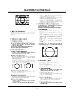
(1) Vertical Position Adjustment
Select VP 0(V-POSITION)and adjust until the mechanical
center point and the center of screen unite.
(2) Vertical Size Adjustment
Select VP 1(V-SIZE) and adjust until the smaller inscribed
circle of Digital Pattern coincides with the outer frame of
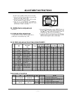
screen as figure below.
And select VP 2(UP-VLIN) or VP 3 (LO-VLIN) and adjust
until the larger inscribed circle of Digital Pattern coincides
with the outer frame of screen as figure below.
(3) Horizontal Position Adjsutment
Select VP 4(H-POSITION) and adjust until left and right
screen are symmetrically equal.
(4) Horizontal Size Adjsutment
Select VP 5(H-SIZE) and adjust until left and right of Digital
Pattern occupy two and half or three blanks.
(5) Pincushion Adjustment
1. Select VP 6(PIN-PH) and adjust until screen makes
perfect rectangle.
2. Select VP 7(AFC-ANGLE) and adjust the vertical slope.
3. Select VP 8(AFC-BOW) and adjust the left and right
crooked line on upper and lower side.
4. Select VP 9(PIN-AMP) and adjust until Pincushion
distortion disspears on left and right side.
5. Select VP 10, 11(UP-CORNERPIN, LO-CORNERPIN)
and adjust until pincushion distortion dispears on upper
and lower side of screen, respectively.
9.3 1081I Mode Deflection Adjustment
This adjustment should be adjusted manually by receiving
1080I signal transmitted in SET TOP BOX.
Adjust after finishing the 480I/P Mode deflection adjustment.
(1) Preliminary Steps
1) Sanction Y, Pb, Pr input of SET TOP BOX to component
2 input termianl.
2) Move the channel of SET TOP BOX and receive digital
pattern.
3) Press the INSTART Key to enter into adjustment mode
and select CXA2150 adjustment mode with CH
D
,
E
Key.
4) Use CH
D
,
E
Key on the R/C to select adjustment
item.
5) Use VOL
F
,
G
Key on the R/C for increase/decrease
of data.
[
1080I output signal is 16:9 screen size basically but for the
convenience of adjustment, it is automatically changed to
4:3 mode while entering adjustment mode.
(2) 1080I Mode Adjustment
In the same way as TV mode deflection adjustment.
1) Vertical Position Adjustment
Select VP 0(V-POSITION) and adjust until the
mechanical center point and the center of screen unite.
2) Vertical Size Adjustment
Select VP 1(V-SIZE) and adjust until the inscribed circle
coincides with the outermost area of the screen.
3) Horizontal Position Adjsutment
Select VP 4(H-POSITION) and adjust until left and right
screen are symmetrically equal.
4) Horizontal Size Adjsutment
Select VP 5(H-SIZE) and adjust until left and right of
Digital Pattern occupy two and half or three blanks.
5) Pincushion Adjustment
1. Select VP 6(PIN-PH) and adjust until screen makes a
perfect rectangle.
<Fig. 5>
0 1 2 3 4 . . . 9
<Fig. 4>
Summary of Contents for C30W46
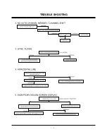
Page 17: ...17 TROUBLE SHOOTING...
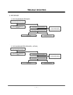
Page 18: ...18 TROUBLE SHOOTING...
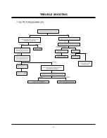
Page 19: ...19 TROUBLE SHOOTING...
Page 20: ...20 TROUBLE SHOOTING...
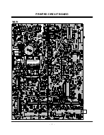
Page 21: ...21 PRINTED CIRCUIT BOARD MAIN...
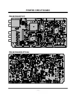
Page 22: ...22 PRINTED CIRCUIT BOARD PROGRESSIVE TOP PROGRESSIVE BOTTOM...
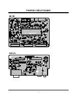
Page 23: ...23 MICOM PRINTED CIRCUIT BOARD SIDE A V...
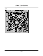
Page 24: ...24 CPT PRINTED CIRCUIT BOARD...
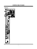
Page 25: ...25 CONTROL PRINTED CIRCUIT BOARD...
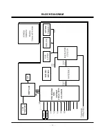
Page 27: ...27 Option BLOCK DIAGRAM...
Page 38: ......
Page 39: ......
Page 40: ......


