Service manual
Carl Zeiss Spectroscopy GmbH
Lamp replacement and calibration
Corona process
Page 1: ...Service manual Carl Zeiss Spectroscopy GmbH Lamp replacement and calibration Corona process...
Page 2: ...re prohibited unless explicit permission has been granted Violations of this copyright notice will result in claims for damages All rights are reserved in case a patent is granted or a sample is regis...
Page 3: ...Laser safety 5 2 Preparing for the lamp replacement 8 3 Determining the device version 9 4 Replacing halogen lamps 16 4 1 General tasks 16 4 2 Determining the lamp type 21 4 3 Removing halogen lamps l...
Page 4: ...mp type 21 Fig 18 Disconnecting the lamp cable lamp type A 22 Fig 19 Unscrewing the lamp holder lamp type A 22 Fig 20 Remove lamp holder lamp type A 23 Fig 21 Removing the halogen lamp lamp type A 24...
Page 5: ...na process spectrometer does not pose any laser beam risks for the operating or service personnel However please observe the following warnings Caution RADIATION ENERGY HAZARD Emissions display The la...
Page 6: ...ess spectrometer must be obeyed Check whether all labels shown in the following diagram are provided If any labels are missing please contact ZEISS Germany or one of the service agencies Fig 1 Carl Ze...
Page 7: ...e laser beam fields and paths Beam path laser triangulation sensor SICK DT20 Hi for Corona process 000000 2074 398 Laser class II Radiation strength 1 mW 0 35 0 9 mW Wavelength 655 nm Window transmiss...
Page 8: ...ivery package Calibration device certified white standard with corresponding certificate accompanying CD Black standard Tools for the lamp change Associated instructions Storage box Ethernet cable ord...
Page 9: ...tware Start the OSISManagementConsole exe under C Program Files x86 ZEISS InProcess C Program Files x86 ZEISS InProcess OSIS ManagementConsole 3 Selecting the device Select the Corona process measurin...
Page 10: ...etermining the device version Lamp replacement and calibration Corona process Fig 4 Entering or scanning the IP address 5 Open the Get device information context menu Right click Corona process then s...
Page 11: ...d calibration Corona process Determining the device version Lamp replacement and calibration Corona process 6 Select the device measuring system Under Please select one entry select Corona process as...
Page 12: ...ntenance or repair If Hardware revision 2 is displayed you may replace the lamps Regardless of the lamp type already installed lamp type B must be mounted see paragraph 4 2 Determining the lamp type o...
Page 13: ...ils button An ini file is created Save this file 10 Carry out firmware update starting from Hardware revision 2 Repeat the work steps from 5 to 7 Starting from Hardware revision 2 a firmware update ha...
Page 14: ...stalled the following warning message will be shown Fig 9 Firmware version warning notification If you have selected the correct firmware the following window appears To start the firmware update clic...
Page 15: ...few minutes Fig 11 Firmware update is being carried out The update was installed successfully Close the notification by clicking OK Fig 12 Confirming successful firmware update The preparation tasks f...
Page 16: ...the measuring system against unintentional power supply by third parties Caution GENERAL HAZARDS All activities listed may only be carried out by service staff of Carl Zeiss Spectroscopy GmbH or train...
Page 17: ...t the activities described below at an ESD work station 4 Prepare spare parts Prepare the following spare parts Spare lamps 2x order no 000000 2219 967 Cable connector screw on 1x Note Always replace...
Page 18: ...nd or using a 22 mm spanner and remove the cables from the device Fig 13 3 2 1 Removing the system cables ETHERNET port Digital IN OUT port POWER 12 24 V DC port power supply 7 Removing the Corona pro...
Page 19: ...hese using a PH2 Phillips screwdriver Caution RISK OF COMPONENT DAMAGE Risk of damaging the FBG filter board while removing the device base from the cover Carefully lift up the base and watch out for...
Page 20: ...the connector panel the default lamp L1 is on the left hand side of the device base and the spare lamp L2 on the right The corresponding labeling is also on the base of the lamp Fig 16 Spare lamp Defa...
Page 21: ...hich lamp type was installed in your device Fig 17 B A Determining the lamp type Halogen lamp type with detachable lamp cable Go to paragraph 4 3 Removing halogen lamps lamp type A on page 22 and foll...
Page 22: ...e lamp socket Place the cable at a spot where it cannot be damaged and does not affect the following work steps Fig 18 1 Disconnecting the lamp cable lamp type A 2 Loosening the lamp holder First remo...
Page 23: ...tion Corona process 3 Removing the lamp holder Carefully remove the lamp holder of the default lamp 1 by lifting it upwards Ensure to not touch the light guides 2 underneath Fig 20 2 1 Remove lamp hol...
Page 24: ...clean surface Remove the three screws 1 from the lamp holder 2 using a TX10 screwdriver and remove the clamping ring 3 Remove the old halogen lamp 4 from the lamp holder Fig 21 2 1 3 2 4 5 4 1 Removi...
Page 25: ...e Unplug the lamp cable Lamp L2 Spare lamp Unplug the lamp cable 3 from the plug in location see Fig 22 Unscrew the cable connectors 2 with a TX 10 wrench Separate the cable connector and remove any o...
Page 26: ...only three of the four screws 2 from the base of the lamp Do this using a TX25 screwdriver To avoid contact with the light guides 4 secure the lamp holder 3 in place and remove the fourth screw Fig 2...
Page 27: ...ugh the lamp holder of the L2 spare lamp Therefore the lamp holder must be removed laterally 4 Removing the halogen lamp Place the lamp holder 5 on a clean surface Remove the three screws 1 from the l...
Page 28: ...sent to the service department Hardware revision 2 requires installation of lamp type B Caution SENSITIVE COMPONENTS When mounting a new lamp 4 ensure that the lamp cable 6 is not crushed bent or oth...
Page 29: ...black marking on the lamp socket 4 1 is pointing upwards in its installation position Fig 27 4 1 6 5 Aligning the halogen lamp Place the clamping ring 3 on the halogen lamp Reinsert the three screws i...
Page 30: ...lamp Guide the lamp cable for lamp L1 back through the device to the circuit board as shown in Fig 22 Reattach the lamp cable to the cable bracket see Fig 22 1 and lock it Reconnect the plug of the l...
Page 31: ...filter board whilst placing the base into the cover Carefully place the base and watch out for stuck or jammed parts and cables Carefully place the base of the device 2 into the device cover 4 by hol...
Page 32: ...process calibration assembly order no 000000 2211 998 Delivery package Calibration device certified white standard with corresponding certificate accompanying CD Black standard Tools for the lamp cha...
Page 33: ...SS InProcess C Program Files x86 ZEISS InProcess OSIS ManagementConsole If not already done so open the menu item New and select the Corona process measuring system Fig 30 Selecting the measuring syst...
Page 34: ...by clicking Yes Fig 32 Resetting the lamp counter 5 Selecting the certificate of the white standard Note Ensure that the white standard certification is still valid The corresponding certificate can...
Page 35: ...nd calibration Corona process Sensor calibration Lamp replacement and calibration Corona process Fig 33 Specifying the white standard Fig 34 Selecting the csv file Note Ensure 15 minutes warm up time...
Page 36: ...impurities Cover it up with the delivered lid when not using it We recommend certifying the white standard once a year Place the white standard in the standard holder at position P6 Fig 35 Mounting th...
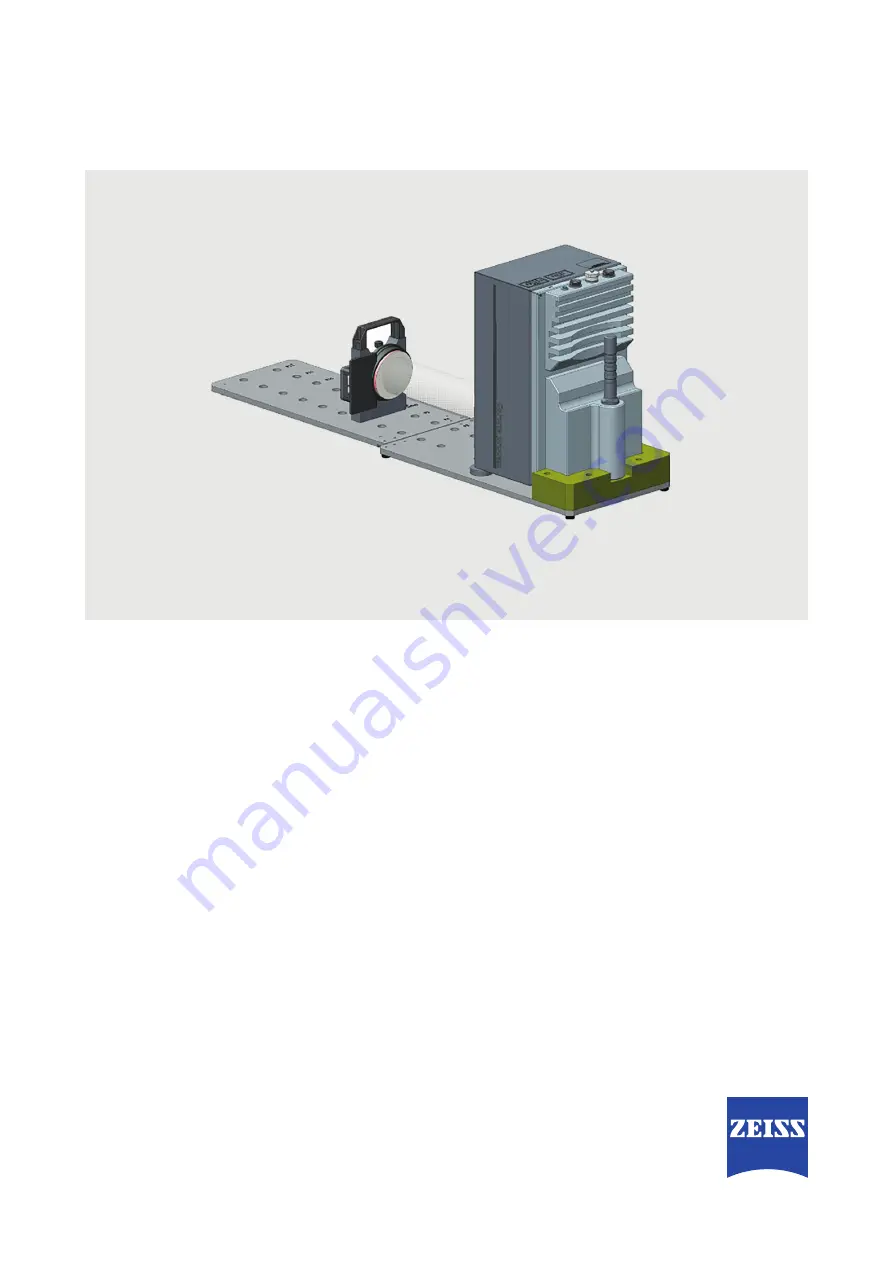
Page 37: ...slide the white standard along its sliding axis 1 to the measurement window 4 of Corona process until touching it Fig 37 4 3 2 1 5 6 Positioning the white standard Keep the white standard 3 in this p...
Page 38: ...placement and calibration Corona process 8 Black calibration Remove the white standard from the holder and place the holder on position P2 Install the black standard to the holder Fig 39 Positioning t...
Page 39: ...Ensure that the white standard touches the measurement window Keep the position by tightening the clamping screw see Fig 37 Fig 41 Continuing the distance correction Press the Continue button to cont...
Page 40: ...ile will be saved in the following folder C ProgramData ZEISS OSIS Device Note Transmit this zip file to ZEISS Service see step 14 Transmit ini files and zip file on page 41 Fig 42 Saving the distance...
Page 41: ...le 14 Transmit ini files and zip file Transmit the second ini file created in step 13 the first ini file created during preparation of the lamp replacement see also chapter 2 step 9 Generate ini file...
Page 42: ...ries and spare parts Accessories Order number Ethernet cable for Corona 3 m 000000 2036 573 Lab power cable 000000 2045 548 Spare parts Order number Spare lamp 000000 2219 967 Service Set Order number...