background image


16 


04/2009 

!


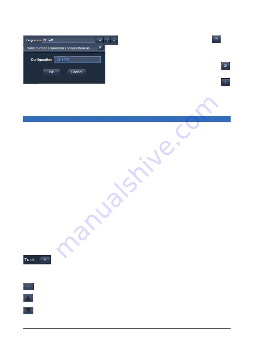
For  storing  a  new  configuration  click 

  and 

enter a desired name in the first line of the list 
box  (Fig.  19),  then  click 

Ok

  to  store  the  con-

figuration. 

!


For  loading  an  existing  configuration  click 


then select it from the list box. 

!


For deleting an existing configuration click 


then select it from the list box and confirm the 
deletion with 

Ok


Settings for multiple track configurations in Channel Mode 

Multiple  track

  set-ups  for  sequential  scanning  can  be  defined  as  one  configuration  (

Channel  Mode 

Configuration

), to be stored under any name, reloaded or deleted.  

The maximum of four tracks with up to eight channels can be defined simultaneously and then scanned 
one  after  the  other.  Each  track  is  a  separate  unit  and  can  be  configured  independently  from  the  other 
tracks with regard to channels, Acousto-Optical Tunable Filters (AOTF), emission filters and dichroic beam 
splitters.  

The  following  functions  are  available  in  the 

List  of


Tracks

  panel  in  the 

Imaging  Setup  Tool

  (Fig.  17, 

Fig. 18 and Fig. 19). 


Switch track

 every 

Line 

Tracks are switched during scanning line-by-line. The following settings can be changed 
between tracks: Laser line, laser intensity and channels. 

Frame 

Tracks  are  switched  during  scanning  frame-by-frame.  The  following  settings  can  be 
changed  between  tracks:  Laser  line  and  intensity,  all  filters  and  beam  splitters,  the 
channels incl. settings for gain and offset and the pinhole position and diameter. 

Frame Fast 

The  scanning  procedure  can  be  made  faster.  Only  the  laser  line  intensity  and  the 

Amplifier


Offset

 are switched, but no other hardware components. The tracks are all 

matched  to  the  current  track  with  regard  to  emission  filter,  dichroic  beam  splitter, 
setting  of  Detector  Gain,  pinhole  position  and  diameter.  When  the 

Line

  button  is 

selected, the same rules apply as for 

Frame Fast


Add Track

 button


An additional track is added to the configuration list in the 

Imaging Setup 

Tool

.  The  maximum  of  four  tracks  can  be  used.  One  track  each  with  basic 

configuration  is  added,  i.e.:  Ch 1  channel  is  activated,  all  laser  lines  are 
switched off, emission filters and dichroic beam splitters are set in accordance 
with the last configuration used.  

 Remove

 button


The track marked in the 

List of Tracks

 panel is deleted.  


A click on this arrow button will move the selected track (highlighted in light 
grey) one position upwards in the list box.  


A click on this arrow button will move the selected track (highlighted in light 
grey) one position downwards in the list box.  


Fig. 19 

Track Configurations window 

Summary of Contents for ConfoCor 3

Page 1: ...011234 5 66...

Page 2: ......

Page 3: ...es from his samples This Quick Guide does NOT replace the detailed information available in the full user manual or in the manual of the respective microscopes Axio Imager Axio Observer Axio Examiner...

Page 4: ...or reflected light illumination via the power supply as described in the respective operating manual Switching on the Ar ML Laser If the Ar ML laser is required switch it on via the toggle switch Fig...

Page 5: ...tes the entire software package for new image acquisition and analysis The Image Processing mode ignores all hardware and activates only data handling and image processing functionality for already ac...

Page 6: ...4 04 2009 Fig 4 ZEN Main Application Window after Startup with empty image container Fig 5 ZEN Main Application Window after Startup with several images loaded...

Page 7: ...the image According to the chosen view tab the required view controls appear in View Control Tabs below each image File management and data handling tools are found in the Right Tool Area see Fig 4 a...

Page 8: ...your personal preferences Fig 7 Setting up conventional confocal software for a specific experiment can take a long time and is often tedious to repeat With ZEN these adjustments have to be done only...

Page 9: ...written by a new scan Multi dimensional scans or saved images will never be over written and a new scan will then automatically create a new image document Acquired data is not automatically saved to...

Page 10: ...File Menu The ZEN File Browser can be used like the WINDOWS program file browser Images can be opened by double click and image acquisition parameters are displayed with the thumbnails Fig 9 For more...

Page 11: ...the lasers are turned on automatically The Laser Life Extender function of the software shuts all lasers off if ZEN is not used for more than 15 minutes To manually switch lasers on or off Click the...

Page 12: ...press the Online button for your actions to take effect immediately Then open the Ocular tool to configure the components of your microscope like filters shutters or objectives Fig 11 Selecting an obj...

Page 13: ...icroscope settings Microscope settings can be stored as configurations Fig 13 by typing a config name in the pull down selector and pressing the save button Fast restoration of a saved config is achie...

Page 14: ...rrow in the dye list and simply choose the dye s you want to use in your experiment from the list dialogue In this dialogue the dyes can be also searched by typing the name in the search field Fig 14...

Page 15: ...n If the option Linear Unmixing is selected the system is set in the lambda mode automatically Pressing the Auto Exposure button will then optimize the settings of the Gain Master and offset for the g...

Page 16: ...uble and triple labeling line by line or frame by frame Advantage Only one detector and one laser are switched on at any one time This reduces cross talk Disadvantage slower image acquisition Open the...

Page 17: ...box of the selected channel Ch 1 4 monitor diode ChM QUASAR detectors ChS1 8 transmission ChD for the scanning procedure and assigning a color to the channel Select the appropriate filters and activat...

Page 18: ...and channels Frame Tracks are switched during scanning frame by frame The following settings can be changed between tracks Laser line and intensity all filters and beam splitters the channels incl se...

Page 19: ...the Acquisition Mode tool Fig 20 to adjust the scan speed A higher speed with averaging results in the best signal to noise ratio Scan speed 8 usually produces good results Use speed 6 or 7 for superi...

Page 20: ...mode in the Acquisition Mode tool Select the number of lines or frames to average Adjusting pinhole size Select the Channels tool in the Left Tool Area Set the Pinhole size to 1 AU Airy unit for best...

Page 21: ...pre adjustment of detector gain and offset Select Live for continuous fast scanning useful for finding and changing the focus Select Continuous for continuous scanning with the selected scan speed Se...

Page 22: ...1 Airy Unit Fig 25 Set the Gain Master high When the image is saturated reduce AOTF transmission in the Laser control section of the Channels Tool Fig 25 using the slider to reduce the intensity of th...

Page 23: ...Stack Then focus on the lower specimen area where the recording of the Z Stack is to end Click on the Set Last button to set this lower position Click on the button to set number of slices to match th...

Page 24: ...r experiment Click on the Save button If you close an image which has not been saved a pop up window will ask you if you want to save it Choosing yes will lead you to the WINDOWS Save As window To exp...

Page 25: ...itch off the Ar ML laser with first the idle run switch Fig 2 3 and second the key switch Fig 2 1 then wait until the fan of the Argon laser has switched off Don t switch off the main power yet On the...

Reviews: