background image

ZEISS 

OPERATION 

Axio Imager 2 


Illumination and contrast methods 


166 

430000-7544-001 

01/2016 


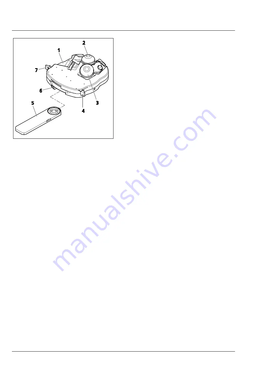
To swivel the brightfield front lens 

H

  into the 

optical path, set lever (Fig. 194/

4

) to position 

I


(darkfield front lens 

D

 swiveled out). To swivel it 

out, set lever to position 

0


Before swiveling the darkfield front lens 

D

 in or 

out, the wide-field DF slider (Fig. 194/

5

) should 

be extracted from the universal condenser 

(outer click-stop position). To swivel this lens in, 
set lever (Fig. 194/

7

) to position 

0

. To swivel it 

out, set the lever to position 

I


For immersion applications, screw the darkfield 

attachment 1.2-1.4 Oil onto the darkfield front 

lens and apply Immersol 518 F

® 

immersion oil. 


(5) 

Use of achromatic-aplanatic condenser 0.9 H/0.4 LD  

The achromatic-aplanatic condenser 0.9 H/0.4 LD is equipped with a 0.9 front lens for brightfield use and 

a second front lens (0.4) for brightfield and phase contrast applications together with slider Ph 1 or Ph 2 

at a working distance of approximately 14 mm.  


The front lenses are swiveled in and out in the same manner as described for achromatic-aplanatic 

universal condenser 0.9 H/0.8-0.9 DF. 


Slider Ph must be removed from the condenser when front lens 0.4 is swiveled in or out. 


Fig. 194 

Achromatic-aplanatic universal 
condenser 0.9 H/0.8-0.9 DF  

Summary of Contents for Axio Imager 2

Page 1: ...Axio Imager 2 Upright microscope Operating Manual...

Page 2: ...ot permitted Persons in contravention of this copyright shall be liable for damages All rights reserved in the event of a patent granted or registration of a utility patent All names of companies and...

Page 3: ...roscope 36 3 5 1 Inserting the eyepiece reticles 37 3 5 2 Compensation of ametropia when eyepiece reticles are used 37 3 5 3 Inserting the fold over eyecups 37 3 6 Setting the interpupillary distance...

Page 4: ...smitted light 62 3 31 VIS LED attachment lamp for transmitted light 64 3 31 1 The VIS LED attachment lamp is only intended for use with transmitted light 64 3 31 2 Adjusting the VIS LED attachment lam...

Page 5: ...ing the motorized microscope via the touchscreen of the TFT display 103 4 8 1 Screen layout 104 4 8 2 Menu structure 107 4 8 3 Home page 108 4 8 4 Favorite page 111 4 8 5 Microscope page 111 4 8 6 Con...

Page 6: ...etting reflected light polarization Detection of bireflection and reflection pleochroism 194 5 CARE MAINTENANCE TROUBLESHOOTING AND SERVICE 196 5 1 Instrument care 196 5 2 Instrument maintenance 197 5...

Page 7: ...rmation and warnings that must be followed by the owner operator personnel The following warning and information symbols are used in this Operating Manual NOTE This symbol indicates an instruction whi...

Page 8: ...rrier The manual microscopes Axio Imager A2 A2 LED A2m D2 and D2m have a power supply integrated in the stand which allows line voltages to be used in the ranges 100 to 127 V and 200 to 240 V AC 10 50...

Page 9: ...nnect the power plug before changing the lamps and allow the instrument to cool down for approx 15 minutes Dust and dirt may impair the instrument s performance The instrument must be effectively prot...

Page 10: ...age if the high performance focus is activated It is essential to read the safety data sheet provided with Immersol 518 F immersion oil Immersol 518 F immersion oil is a skin irritant Avoid contact wi...

Page 11: ...motorized stands Fig 2 STOP button The STOP button on the TFT display switches off the movement of the focusing drive instantaneously to prevent a collision with the stage or the specimen placed on i...

Page 12: ...ZEISS INTRODUCTION Axio Imager 2 Warning labels 12 430000 7544 001 01 2016 Fig 4 Warning labels on the VIS LED attachment lamp Fig 5 Warning labels on the underside of the microLED...

Page 13: ...shall invalidate any warranty claims With the exception of the work described in this Operating Manual no maintenance or repair work is to be carried out on the Axio Imager 2 Repairs may only be perf...

Page 14: ...1 01 2016 1 5 Overall view of Axio Imager 2 coded 1 Eyepieces 2 Binocular tube 3 Reflected light illuminator HBO 100 4 Microscope stand manual 5 Transmitted light illuminator HAL 100 6 Mechanical stag...

Page 15: ...Overall view of Axio Imager 2 motorized 1 Eyepieces 2 Binocular phototube 3 Reflected light illuminator HBO 100 4 Microscope stand motorized 5 Transmitted light illuminator HAL 100 6 TFT display 7 Mec...

Page 16: ...ions in laboratories research clinics and medical practices Science and research colleges universities in the fields of medicine and biology Industrial applications pharmacology food technology Typica...

Page 17: ...nds is variable and can be customized to the user s requirements within the range of optional microscope components Coded models Axio Imager A2 A2m and A2 LED Partially motorized models Axio Imager D2...

Page 18: ...6x motorized HD DIC ACR O O O O 7x coded HD O O O O O O O O O 7x motorized HD O O O O Modulator turret for C DIC TIC manual O O O O O O O O O O motorized O O O O Modulator turret for transmitted light...

Page 19: ...O O O Power supply External Internal Mechanical CAN stages motorized O O O O O O O O O O Scanning stages Piezo O O O O O O O O O O DC stepper motors O O O O O O O O O O Fast z piezo operation With man...

Page 20: ...ZEISS INSTRUMENT DESCRIPTION Axio Imager 2 System overview of Axio Imager 2 20 430000 7544 001 01 2016 2 4 System overview of Axio Imager 2 Condensers...

Page 21: ...Axio Imager 2 INSTRUMENT DESCRIPTION ZEISS System overview of Axio Imager 2 01 2016 430000 7544 001 21 Microscope stages...

Page 22: ...ZEISS INSTRUMENT DESCRIPTION Axio Imager 2 System overview of Axio Imager 2 22 430000 7544 001 01 2016 Tubes eyepieces...

Page 23: ...Axio Imager 2 INSTRUMENT DESCRIPTION ZEISS System overview of Axio Imager 2 01 2016 430000 7544 001 23 Tube carrier objective nosepiece...

Page 24: ...ZEISS INSTRUMENT DESCRIPTION Axio Imager 2 System overview of Axio Imager 2 24 430000 7544 001 01 2016 Modules sliders filters...

Page 25: ...Axio Imager 2 INSTRUMENT DESCRIPTION ZEISS System overview of Axio Imager 2 01 2016 430000 7544 001 25 Illumination...

Page 26: ...ZEISS INSTRUMENT DESCRIPTION Axio Imager 2 System overview of Axio Imager 2 26 430000 7544 001 01 2016 Documentation...

Page 27: ...r ring on objective Black Brown Red Orange Yellow Green Light blue Dark blue White Magnification factor 1x 1 25x 2 5x 4x 5x 6 3x 10x 16x 20x 25x 32x 40x 50x 63x 100x 150x Objective magnification multi...

Page 28: ...x 23 Br foc and E PL 10x 23 Br Foc is 23 mm W PL and PL in the eyepiece designation indicates excellent image flatness up to the edge of the field of view If required eyecups for the eyepieces can be...

Page 29: ...at 1 mm intervals in y direction 100 lines at 1 100 mm intervals in y direction 25 lines at 1 mm intervals in x direction 50 lines at 1 10 mm intervals in x direction Circular areas with diameter of...

Page 30: ...h x height Axio Imager stand manual with HBO 100 approx 300 mm x 721 mm x 505 mm Axio Imager stand motorized with HBO 100 and TFT display approx 390 mm x 721 mm x 505 mm Weight Axio Imager 2 coded mot...

Page 31: ...e voltage for external power supply VP232 2 100 V to 240 V 10 Line frequency 50 Hz 60 Hz Power consumption of coded Axio Imager max 300 VA Power consumption of motorized Axio Imager max 190 VA LED ill...

Page 32: ...Stand with motorized stage focusing Step size of stepper motor 25 nm Axio Imager M2 10 nm Axio Imager Z2 Rapid lowering lifting of stage 10 mm Lifting range 25 mm Height stop electronic Focusing speed...

Page 33: ...r spare lamp dust cover tool bag with tools The following components are factory mounted onto the microscope stand mechanical stage specimen holder objectives polarizer filter holder reflected light i...

Page 34: ...ventilation floor impact noise or other shocks can have an impact on the supplementary modules of the microscope some of which react sensitively It can also lead to reduced image quality and experime...

Page 35: ...stand as described below Use an AF 3 ball headed screwdriver to undo clamping screw Fig 10 4 and remove the tube Fig 10 2 upwards Place dust cap Fig 10 3 for tube lens protection on the dovetail of t...

Page 36: ...rt tube Fig 11 1 without tube lens and dovetail into the mount of the tube lens turret Fig 11 6 and tighten clamping screw Fig 11 3 3 5 Inserting the eyepieces and auxiliary microscope Remove both dus...

Page 37: ...focusing lens of the adjustable eyepiece to focus on the line figure of the eyepiece reticles Viewing through the eyepiece use the focusing drive to focus the microscope image of a specimen placed on...

Page 38: ...erpupillary distance is correct when you see only one round image while looking through the two eyepieces 3 7 Setting the viewing height The viewing height can be adjusted to individual requirements b...

Page 39: ...th microphotographic devices consult the corresponding manuals of the cameras as well Fix the camera adapter 60N Fig 16 1 2 to the camera Remove the dust cap from the camera port Please note The three...

Page 40: ...reflector turret or modulator turret only when the microscope is switched off Loosen the clamping screw Fig 18 1 Pull out the reflector turret Fig 18 6 or the cover part using the grip recess conditio...

Page 41: ...ting hole Holding it by the handles Fig 19 5 to the right and left of the module insert the module Fig 19 6 obliquely from the bottom into the upper spring clips Fig 19 1 on the reflector turret Then...

Page 42: ...onto a soft surface Insert the barrier filter emission filter at Fig 20 2 the exciter filter at Fig 20 5 Secure both filters by means of retaining rings Fig 20 1 The barrier filter and exciter filter...

Page 43: ...21 7 mark the illumination and imaging beam path 3 13 Changing the beam splitter in the reflector module FL P C When mounting filters and beam splitters take extreme care to prevent damage to and con...

Page 44: ...insert both parts together into the bottom half of the module Ensure that the side tongue of the spring loaded frame is in the appropriate recess in the bottom half of the module The reflective coate...

Page 45: ...the condenser carrier Fig 25 2 and the stage carrier Fig 25 9 Turn the set screw on the bottom of the condenser towards the groove Fig 25 3 Tighten the clamping screw Fig 25 4 on the condenser mount T...

Page 46: ...until the DIC prism to be replaced appears in the blank aperture Fig 27 4 Hold the disk by its knurled ring Unscrew the retaining ring using the so called dual function tool Fig 27 2 Then screw the to...

Page 47: ...he recess of the mount provided in the modulator turret Ensure that the labeling on the knurled ring of the turret disk is correct For correct operation it is necessary to inform the system of the ame...

Page 48: ...or reflected light transmitted light stage carrier 430704 9901 000 or 430701 9901 000 screw the lower stop screw into the lower tapped hole Fig 30 4 Upper stop screw Fig 30 6 When an 18 mm thick micr...

Page 49: ...arrier see Section 3 17 Loosen the four clamping screws Fig 31 1 to 4 of the dovetail guide Move the guide plate Fig 31 5 as far up as it will go in the slots Then tighten the four screws Always proce...

Page 50: ...fine focusing drive to the right and left on the stand can be provided either with a fine drive knob or a fine drive disk To change the fine drive knob or the fine drive disk proceed as follows Turn t...

Page 51: ...n the filter opening filter wheel 1 Fig 34 2 or filter wheel 2 Fig 34 4 The figure indicates the transmission in of the set filter position Set the desired position on the filter wheel Insert the corr...

Page 52: ...vant position with the reflective coating side up Ensure that no dirt gets onto the filter surface Screw in the retaining ring After all filters have been inserted put on the cover plate and screw it...

Page 53: ...ated to protect the focusing drive Once the high performance focus has been activated specimen weights of up to 5 kg can be placed on the stage Reading the status of the high performance focus on the...

Page 54: ...e Fig 37 4 The head of the locking pin is now no longer visible and the high performance focus is inactive Use the Z drive to move the microscope stage into the working position 3 24 Mounting the TFT...

Page 55: ...display is already mounted on the motorized stand it should first be removed The mounting holes and the opening for the plug in contact on the stand must then be sealed with the caps supplied Apply t...

Page 56: ...asten the bottom part of holder Z Fig 40 5 with both screws Fig 40 4 to the stage carrier Insert the focus linear sensor Fig 40 1 in the top part bring it into line with the lower edge and fasten it b...

Page 57: ...unit automatically adapts to the line voltage available 3 28 2 Motorized stand Insert the connecting plug Fig 42 2 of power supply VP232 2 Fig 42 3 into the corresponding socket Fig 42 1 on the rear...

Page 58: ...flected light or transmitted light socket Insert the dovetail mount of the lamp housing Fig 43 9 into the corresponding socket Fig 43 2 or Fig 43 6 and using the SW 3 ball headed screwdriver tighten i...

Page 59: ...W power supply Set the transmitted light reflected light toggle switch Fig 44 3 to the position for reflected light RL Use a power cord to connect the power connector Fig 44 5 to a power outlet For re...

Page 60: ...the reflected filament image Fig 46 1 2 Fine adjustment Reattach the microscope illuminator to the microscope stand and lock it with the clamping screw Turn off the diffusion disk for reflected or tra...

Page 61: ...or 12 V 100 W Fig 43 3 reflected light or Fig 43 5 transmitted light and allow to cool down for approximately 15 minutes Depress unlock button Fig 47 3 of halogen illuminator HAL 100 Fig 47 1 extract...

Page 62: ...nator on the transmitted light port Loosen clamping screw Fig 48 1 on transmitted light port Fig 48 2 Remove the halogen lamp Disconnect the illuminator plug from the 12 V 100 W connector transmitted...

Page 63: ...nderside of the condenser carrier Fig 49 1 Move it upwards so that the bolts Fig 49 5 fit into the corresponding holes on the illuminator Fasten the illuminator by means of the countersunk screws Fig...

Page 64: ...ded screwdriver and clamping screw Fig 50 1 to lock the attachment lamp Fig 50 3 with dovetail mount firmly into socket Fig 50 2 Connect the three pin illuminator plug Fig 50 5 to the lower three pole...

Page 65: ...chment lamp is only intended for transmitted light operation Do not look directly into the LED light Only insert or remove the microLED attachment lamp in from the transmitted light port while switche...

Page 66: ...The gray filters mounted in the 2 position filter wheels 428300 9901 000 or 428301 9901 000 are not permanently stable Only the gray filter set 487935 9020 000 can be used 3 33 2 Attaching the HBO 100...

Page 67: ...illuminator Fig 56 1 via the HBO 100 transformer Fig 85 2 and allow it to warm up to the operating temperature Pull adjusting aid Fig 55 1 out of the microscope stand The brighter arc spot of the HBO...

Page 68: ...rol via the CAN USB converter is not possible To install the switching mirror proceed as follows If necessary remove the illuminator if already mounted To do so grip the illuminator firmly and loosen...

Page 69: ...connector for camera synchronization 6 LM set button for light manager function 7 RS 232 port 3 34 2 Motorized stand Key to Fig 59 1 CAN port 2 USB port 3 Ethernet port 4 RS232 port 5 CAN port 6 CAN p...

Page 70: ...rrier assembly is then turned over and fixed to the stage carrier dovetail 3 35 1 Fixed mechanical stage 75x50 R 1 Removing the stage Unscrew the four fastening screws Fig 60 3 on stage carrier Fig 60...

Page 71: ...ge to the front against spring pin Fig 63 4 lift it off the stage carrier Fig 63 2 from the back and remove it upwards Retighten screw cap Fig 63 3 2 Attaching the stage Loosen screw cap Fig 63 3 from...

Page 72: ...to the eyepiece reticles Reset the two centering screws on the stage carrier Fig 64 2 using one SW 1 5 Allen screwdriver Fig 64 5 each to move the specimen detail by half the arrow length in the direc...

Page 73: ...ctory set to an average torque You can change this setting as follows 1 Adjusting the x direction Remove the additional sleeves Fig 65 1 and 3 from the drive knobs if necessary Loosen the clamping scr...

Page 74: ...anical stage with the slots under the heads of the knurled screws and tighten it using the knurled screws 3 36 Rotary stage Pol 3 36 1 Removing the rotary stage Pol Loosen screw cap Fig 67 2 from the...

Page 75: ...e when the stage is rotated the set specimen detail will remain in the center of the image If the detail moves out of the center of the field of view Fig 68 5 while rotating the stage the stage should...

Page 76: ...1 To center the stage use a high contrast specimen and an eyepiece with crossline reticle First turn the nosepiece to swing the non centerable objective mount Fig 69 1 mount with DIC slot into the lig...

Page 77: ...Slide the stage plate Fig 70 1 forwards and fasten coaxial drive Fig 70 4 to the underside of the stage using two screws Fig 70 5 Place mechanical stage Fig 70 1 onto the stage carrier so that the hol...

Page 78: ...onnect the CAN connection socket on the mechanical stage Fig 71 2 to that on the rear of the stand using a CAN bus cable The motorized stages can be connected directly to the M2 M2m Z2 Z2m stands via...

Page 79: ...cal stage coincide with the through holes of the stage carrier Using the angled Allen key AF 3 screw four screws Fig 70 6 from the bottom into the underside of the stage with the shorter screws being...

Page 80: ...connect the USB port of the PC to the CAN USB converter Fig 73 3 Connect the DC voltage input terminal of the CAN USB converter Fig 73 2 24 V DC 1 25 A to the plug type power supply output output 24 V...

Page 81: ...the focusing drive to the right corresponds to Fig 74 1 on the docking station can be operated via the docking station detached from the stand Default button allocation can be altered via the TFT disp...

Page 82: ...screws Fig 75 2 to the condenser carrier using holes Fig 75 6 and 7 Hold the polarizer Fig 75 4 parallel to the bottom side of the condenser carrier Using the offset adjusting lever Fig 75 3 screw th...

Page 83: ...ZEISS Coded Axio Imager 2 coded operation and function controls 01 2016 430000 7544 001 83 4 OPERATION 4 1 Coded Axio Imager 2 coded operation and function controls Fig 76 Axio Imager 2 coded operatio...

Page 84: ...els discrete see page 86 16 Lever for transmitted light diffusing glass see page 86 17 Control wheel for luminous field diaphragm see page 86 18 Focusing drive Fine focusing control right side see pag...

Page 85: ...th deflection left Fig 76 4 Switching the optical path to the camera path deflection left with interface 60N The camera path deflection may optionally be equipped with 50 beam splitter or with 100 def...

Page 86: ...ks the transmitted light path function corresponds to Fig 76 29 The monitoring LED lights up when the shutter is open Light intensity control Fig 76 14 Used to adjust the d c voltage supply of the hal...

Page 87: ...mit facilitates finding the K HLER illumination position again Polarizer for transmitted light Fig 76 24 Various types of transmitted light polarizers are available with fixed or rotatable polarizer o...

Page 88: ...r DIC slider or seven M27 objective mounts Objectives are quickly changed objective position by turning the knurled ring of the objective nosepiece Reflector turret Fig 76 27 With six mounts for repla...

Page 89: ...th 4 2 Axio Imager 2 operation and function controls motorized version In this section the operation and function controls of the motorized version of the Axio Imager are described that are different...

Page 90: ...ZEISS OPERATION Axio Imager 2 Axio Imager 2 operation and function controls motorized version 90 430000 7544 001 01 2016 Fig 80 Axio Imager 2 operation and function controls motorized version...

Page 91: ...diaphragm 14 Button for quick action lowering of stage LOAD POSITION see page 93 15 Button for quick action lifting of stage OPERATING POSITION see page 94 16 Button setting depends on stand type 17...

Page 92: ...ig 80 7 When using the HAL 100 halogen illuminator in the reflected light and the transmitted light path the double filter wheel discrete mot can be used for brightness adjustment This contains four f...

Page 93: ...r Fig 824 for forwards or backwards Motorized focusing drive coarse fine Fig 80 8 on both sides of stand This is operated manually by turning the coarse or fine focusing controls on both sides of stan...

Page 94: ...t switch on the power supply VP232 2 at its on off switch Fig 85 1 and then operate the on off switch on the stand Position I Set the desired light intensity using the light intensity control If you i...

Page 95: ...mot The 2TV tube mot Fig 86 is available for all Axio Imager stands of type M2 M2m and Z2 Z2m It is mounted on the coupler plate like any other binocular tubes and connected via CAN bus to the stand T...

Page 96: ...addition the 2TV tube has two receptacles Fig 89 1 and 2 into which P C modules Fig 89 3 can be inserted One of these receptacles is factory fitted with a 100 mirror allowing 100 of the light to be d...

Page 97: ...ntrast methods brightfield phase contrast DIC darkfield polarization for the reflected light contrast methods brightfield darkfield DIC polarization and for reflected light fluorescence When working i...

Page 98: ...tionally have to use neutral density filters to achieve a comparable impression of the specimen 4 6 2 Light Manager Mode CLASSIC If the Light Manager is operated in CLASSIC mode the operator can choos...

Page 99: ...only if it is impossible to achieve optimum illumination through the neutral density filters The computed values are automatically stored in the temporary memory of the microscope As in CLASSIC mode...

Page 100: ...ctive is swung into the light path for which the light intensity has already been set the system will automatically set the corresponding stored value The light intensity settings of the halogen lamp...

Page 101: ...evels the intensity of the halogen lamp is varied by changing the lamp voltage This of course also changes the color temperature for specimen observation The luminous field diaphragm is adapted to the...

Page 102: ...t Pol Polarization contrast Reflected light Reflector turret motorized modulator turret Transmitted light Analyzer in the reflector turret polarizer in the condenser turret and front lens illuminator...

Page 103: ...y This variety of possible ways to select or operate a contrast method may seem confusing at first In fact however it grants the user maximum flexibility since only a maximum of two different TFT page...

Page 104: ...s for activating all pages Which buttons are available depends on the page currently being displayed However the following buttons are accessible on all pages Home Activates the start page Favorites C...

Page 105: ...configured halogen or LED illuminators are controlled directly If no illuminator has been configured the control buttons will not appear 3 Control This area contains control elements dependent on the...

Page 106: ...H D Ph DIC DF Darkfield Transmitted light motorized achr apl condenser 0 9 H D Ph DIC or motorized LD condenser 0 8 H D Ph DIC Reflected light Motorized reflector turret with darkfield module C DIC T...

Page 107: ...ace Navigation bar Level 1 start page Navigation bar Level 2 Tabs in the control area Level 3 Home Page 108 Home Page 108 Favorite Page 111 Favorite Page 111 Microscope Page 111 Turret Page 112 Object...

Page 108: ...ion bar or the Home page 4 8 3 Home page After being switched on the microscope is initialized This process takes a few seconds The Home page Fig 94 appears when the instrument is first started up If...

Page 109: ...n be interrupted using the STOP button Fig 96 or any button on the stand base When the stage arrives in the load position the Load Position popup window Fig 97 appears with the following control eleme...

Page 110: ...top reached appears Under normal focusing drive operation a pop up window Fig 99 appears as soon as the upper or lower limit stop is reached Reflected light illumination button Fig 100 1 The Off and O...

Page 111: ...witched to brightfield Reflector turret switched to the nearest HAL position Halogen transmitted light Light path switched 100 to eyepieces 4 8 4 Favorite page In order to increase the operation effic...

Page 112: ...the magnification and where applicable the following additional information Oil Oil immersion objective W Water immersion objective Imm Immersions There is no operation page for objectives with coded...

Page 113: ...pending on the reflector turret installed 6 or 10 control elements for reflector positions 1 to 6 or 1 to 10 will appear The reflector modules already configured are recognizable by the text showing o...

Page 114: ...Zero button to set the mid position Turn the rear setscrew to set the shift value Each click stop position of the setscrew corresponds to a 0 05 mm change Press the Zero button to reset the value to 0...

Page 115: ...ence is that only the azimuth value needs to be set There is no Zero button The tab will not be available if no motorized reflector turret is installed 5 Tube lens tab Depending on the type of tube le...

Page 116: ...smitted light F A RL Field and aperture diaphragm control in reflected light 1 Light path tab The light path of the microscope on the imaging side is shown in a schematic diagram beneath the Light pat...

Page 117: ...the remaining light path by pressing the Open and Close buttons This tab will not be available if there is no light switch One of the following schematic diagrams or a similar one is displayed in the...

Page 118: ...eyepiece Top Port and a dichroic beam splitter are active at the Back Port The active light paths are displayed in yellow inactive light paths appear in extra light gray line width 1 pixel The line wi...

Page 119: ...ath for Top Port is unknown No motorized camera path deflection installed at Side Port 2 Illumination tab The lamp voltage in transmitted and reflected light and the filter wheels can be monitored her...

Page 120: ...mpletely separately or jointly The desired illuminator is selected via the On or Off buttons on the TFT the light control buttons or if there is no transmitted light shutter it can also be selected di...

Page 121: ...relation to the physical aperture of the diaphragms Configuration of objectives and eyepieces available Diaphragm aperture data are presented for the field number of the eyepieces and aperture of the...

Page 122: ...s being run These can be simple settings or a camera snapshot or even a complex experiment The selection is made under the My AxioVision menu item These functions are only active when the AxioVision s...

Page 123: ...sible no XY controls Measure tab not accessible Manual stage manual Z focusing drive XYZ page is not accessible During microscope initialization the system detects whether a stage is installed Thus th...

Page 124: ...desired XYZ position If the Z value is to be stored activate the incl Z check box Press the Save Position button The Current positions save as pop up window opens Fig 123 There are five buttons Pos 1...

Page 125: ...perform simple distance measurements in millimeters mm Three options are available for these measurements Distance between two manually set positions Distance between a manually set position and a de...

Page 126: ...ctions TL RL switching the control ranges of the illuminators HAL LED and VIS LED Light Manager calculation and Contrast Manager depend on this The Config page provides access to the following pages C...

Page 127: ...uration procedure press the Save button To abort the procedure press the Cancel button From list button The user chooses a magnification from the Preselect Magnification list and an appropriate object...

Page 128: ...ixed six zeros or the affixed seven zeros should not be entered after 123456 enter a hyphen or enter 1234 567 and press OK The missing zeros will be added automatically If a nosepiece and objectives w...

Page 129: ...The current selection is displayed in the Resulting Configuration line Press the button for RL and or TL as appropriate Press the Save button If the turret position has already been configured a confi...

Page 130: ...in Section 4 11 on page 157 Configuring a reflector position using Colibri as a source of illumination Once Colibri has been recognized and configured as a source of illumination an appropriate LED c...

Page 131: ...n this tab Focus Speed The tab contains up to seven buttons depending on the actual number of objective mounts on the nosepiece The number of turret positions is detected by the system during initiali...

Page 132: ...lues remain in the memory of the device after deactivation Use the Adjustment button to start the parfocality alignment On pressing this button a wizard appears to guide you through the procedure If a...

Page 133: ...usually the objective with the highest magnification and air immersion The position to be moved to on coded objective nosepieces is displayed on the LED bar graph However if a motorized objective nos...

Page 134: ...uipped with a software focus limiter which can be set by users They can be globally switched On or Off here Once the software limit function is active the focus delimiter can also be set and altered u...

Page 135: ...ubsequently travels forward toward the user This allows the specimen to be changed easily Parcentricity In this section a so called parcentricity alignment can be carried out for the objectives config...

Page 136: ...coordinates when changing objectives 5 Camera ports tab This tab allows you to configure the adapters and beam splitters beam splitting mirrors reflecting mirrors for the camera ports Top Port Back P...

Page 137: ...io list Press the buttons for the desired splitting ratio multiple selections are possible Press the Save button to store the selected splitting ratio Press the Cancel button to close the window witho...

Page 138: ...Illumination RL Motorized DIC turret Manual condenser Field of view of eyepieces Tube lens turret Reflected light configuration Illumination TL The light source to be employed for transmitted light m...

Page 139: ...tion is automatically linked with the selection of an allocated reflector module This means that the user does not have to consider any additional components Sources of illumination None HAL int HAL e...

Page 140: ...be made here as the positions for C DIC TIC and brightfield are always fixed Field of view of eyepieces The user chooses the eyepieces to be employed in the Field of view eyepiece selection pop up wi...

Page 141: ...is fully integrated in the light and contrast manager This means the following Plate If the contrast manager is used any front lens is swiveled out as soon as the fluorescence function is selected and...

Page 142: ...binations neutral density color and neutral density filters are offered for second generation Axio Imager 2 units These filters are fully integrated into the light manager functions For the sake of cl...

Page 143: ...vated all other options on this tab are grayed out If a Bino Shutter is installed and dazzle protection has been activated the two other dazzle protection fields TL RL are inactive Dazzle protection i...

Page 144: ...ay 144 430000 7544 001 01 2016 6 Miscellaneous This tab is used to calibrate the TFT display 4 8 6 3 Info page The Info page only contains the Firmware tab This tab allows the user to identify the fir...

Page 145: ...7 1 User selection page The User selection page contains a tab for selecting a previously created and configured user A default user may also be chosen This user contains the standard assignment of t...

Page 146: ...Left drive knob Buttons on right Right drive knob Docking station buttons Favorites page Select favorites page 1 HW Settings tab As many as ten hardware settings can be assigned to each user Each sett...

Page 147: ...he OK button or discard the entry by pressing the Cancel button 2 User Settings tab This tab allows the password for the user to be changed Press Change password Enter the old password Enter the new p...

Page 148: ...rol buttons on the left hand side of the stand can be assigned on this tab Click on the top left button pair Use the arrow buttons to select the desired assignment Acknowledge with OK or discard with...

Page 149: ...utton pair Use the arrow buttons to select the desired assignment Acknowledge with OK or discard with Cancel Use the same method for all other button assignments 5 Docking Station tab To assign the do...

Page 150: ...tion prompt 4 8 7 3 Admin page There are two tabs on the Admin page Settings User administration 1 Settings tab The following settings can be defined on this tab Language Active illumination after swi...

Page 151: ...t was turned off Start page after start up The page to be shown after starting the microscope can be defined here There are two options User selection Primarily of interest for multi user operation Fa...

Page 152: ...transferred from an existing user the Adopt user settings checkbox must be activated Pressing Factory Settings then opens another pop up menu The user whose settings are to be adopted can be chosen h...

Page 153: ...e Display off button turns the TFT display off Pressing that button a second time switches the TFT display on again delete To dim the TFT display press the Display button on the navigation bar for mor...

Page 154: ...t the camera to the center of the beam path to center the illumination Search for a reference object on the calibrating specimen cross hairs or similar which is then superimposed on the crosshairs of...

Page 155: ...d Inverted CAN bus 180 rotation Inverted Ludl MAC 6000 180 rotation Inverted Camera on side port q WSB05 WSB08 Horizontal reflection Inverted SMC 2009 Vertical reflection Inverted Inverted CAN bus Hor...

Page 156: ...efine the zero position of the stage and the polarity of the axes 2 If necessary select a suitable specimen holder carrier slide etc in the software 3 Set a reference point on the sample carrier slide...

Page 157: ...ocated to the microscope via the PC application MTB 2011 config exe ACR greatly simplifies microscope work because users can be sure at all times that the configuration displayed on the microscope TFT...

Page 158: ...elect Menu Extras User defined filters New filter sets can be created in this menu 4 Insert a rewritable reflector module P C in the ACR reflector turret and note the position see Fig 19 on page 41 An...

Page 159: ...e configuration software Currently 3 pre defined filter sets can be ordered from ZEISS a 487931 9901 000 This is the standard grey filter set for all brightfield applications b 487935 9010 000 This gr...

Page 160: ...r the user The equipment of the universal condensers is defined using the MTB 2011 config exe configuration program Other options can be set for the DIC and the DF position the number of the prism a p...

Page 161: ...field microscopy For the use of the achromatic aplanatic universal condenser 0 9 H 0 8 0 9 DF refer to Section 4 12 2 4 3 Setting transmitted light brightfield according to K HLER The microscope shoul...

Page 162: ...g 191 D When changing the condenser the luminous field diaphragm normally remains centered unless the centering screws have been adjusted To adjust the aperture diaphragm contrast remove one eyepiece...

Page 163: ...ld diaphragm can also be used for better contrasting by reducing its opening to a certain range Avoid closing it too far otherwise this will impair the evenness of the field of view illumination 4 Set...

Page 164: ...he screw on darkfield attachment 1 2 1 4 Oil 424218 0000 000 3 Setting transmitted light darkfield Set K HLER illumination in the same way as for transmitted light brightfield However use the objectiv...

Page 165: ...se of the achromatic aplanatic universal condenser 0 9 H 0 8 0 9 DF The achromatic aplanatic universal condenser 0 9 H 0 8 0 9 DF Fig 194 1 is equipped with a front lens for brightfield Fig 194 3 and...

Page 166: ...immersion applications screw the darkfield attachment 1 2 1 4 Oil onto the darkfield front lens and apply Immersol 518 F immersion oil 5 Use of achromatic aplanatic condenser 0 9 H 0 4 LD The achroma...

Page 167: ...on the phase position This interference results in differences in intensity and color in the image which are perceptible to the human eye 2 Instrument equipment Phase contrast objectives with phase r...

Page 168: ...e the phase stops are factory centered and the centering is retained even if the universal condenser is removed from the condenser carrier and re attached To enhance the image contrast an interference...

Page 169: ...ntaining DIC prisms DIC I DIC II DIC III Analyzer module D DIC P C 424921 9901 000 in reflector turret Only this module may be used on the Axio Imager 2 as it provides a homogeneous field of view in c...

Page 170: ...junction with histological sections The same applies to acrylic glass culture chambers if the chamber bottom is made of plastic In these cases it is advisable to use chambers with bottom plates of gla...

Page 171: ...light On the modulator turret swivel in the appropriate DIC prism by pressing knob Fig 198 1 for forward rotation or knob Fig 198 2 for backward rotation of the turret Adjust the luminous field diaph...

Page 172: ...ey exhibit four bright and four dark positions when rotated through 360 between crossed polarizers Dependent on the birefringence thickness and orientation of the specimen interference colors ranging...

Page 173: ...tion e g of optically uniaxial or biaxial crystals is oriented parallel to the direction of observation 4 12 5 2 Determining the vibration direction n 1 Application The determination of the vibration...

Page 174: ...n oriented NE SW By moving the compensator into the light path the specimen changes its color The nature of the color change depends on the orientation of the specimen NE SW or NW SE The changes in co...

Page 175: ...el to the principal vibration direction n of the compensator i e NE SW the path difference of the specimen e g grayish white 150 nm and the path difference of the compensator red 550 nm are added toge...

Page 176: ...ectly under the center of the reticle Restrict the size of the aperture to a value of about 0 2 Rotate the rotary stage Pol until the specimen is in extinction position i e it appears entirely dark On...

Page 177: ...mains white It is then however a higher order white and thus the path difference is 5 The appropriate compensator is Tilting compensator K 0 30 Accessory 000000 1115 698 A dark gray as interference co...

Page 178: ...htfield according to K HLER see Section 4 12 1 3 Center rotary stage Pol and objectives if not yet completed see Sections 3 36 3 3 36 4 For the further settings do not use a specimen initially Push th...

Page 179: ...ndependently of the stage rotation in their specific interference color This is determined by the material specimen thickness and orientation To obtain a high contrast image at high objective magnific...

Page 180: ...open cone In practical microscopy this means that the condenser front lens 0 9 or 1 4 must be in the light path the aperture diaphragm fully open and the objective should also have a large aperture 1...

Page 181: ...he focusing drive Check the centering of the objective by rotating the microscope stage Recenter it if necessary Turn the front push pull rod Fig 203 2 to close the luminous field stop until only the...

Page 182: ...hen you rotate the stage It can be located inside or outside the imaged objective pupil depending on the position of the section With optically biaxial crystals the cross resolves into two dark hyperb...

Page 183: ...rasting techniques the 6x20 compensators must be removed from the light path slot for compensators 1 Application Reflected light brightfield microscopy is the simplest and most widely used microscopy...

Page 184: ...of the objective To do so either pull out the adjusting aid or remove one eyepiece from the binocular tube Afterwards push the adjusting aid in again or reinsert the eyepiece Move the reflected light...

Page 185: ...Axio Imager 2 OPERATION ZEISS Illumination and contrast methods 01 2016 430000 7544 001 185 Fig 205 Microscope settings on Axio Imager MAT in reflected light brightfield...

Page 186: ...r Epiplan objectives additionally labeled HD Reflector module DF P C 6x20 compensator mount with darkfield stop for reflected light 424706 0000 000 or 4 position modulator turret 3 Setting reflected l...

Page 187: ...described in Section 4 12 7 for reflected light brightfield Open the luminous field diaphragm until the edge just disappears from the field of view to avoid reflections Rotate the reflector turret to...

Page 188: ...his corresponds approximately to the extinction position best contrast 5 Setting the reflected light DIC with motorized four position modulator turret for circular DIC TIC Prepare the microscope for r...

Page 189: ...e 6x20 compensator mount Fig 206 4 or rotate turret wheel Fig 207 5 of the 4position modulator turret Fig 206 6 into TIC Position TIC Colored interference fringes appear in the field of view Turn the...

Page 190: ...is aperture dependent and decreases with increasing illumination aperture Accordingly the following correction values must be taken into account depending on the objective used Objective Correction f...

Page 191: ...ire object with a homogeneous layer and then measuring the path difference If the layers or steps are transparent e g silicon dioxide on silicon the interference fringes may change their color Determi...

Page 192: ...ctly matched from a spectral viewpoint They are arranged in a reflector module FL P C together with the corresponding dichroic beam splitter 2 Instrument equipment Recommended objectives EC Plan Neofl...

Page 193: ...enter the aperture diaphragm to the exit pupil using the two centering screws Fig 211 3 and 5 if necessary Reinsert the eyepiece in the tube and close the luminous field diaphragm Fig 211 7 until it i...

Page 194: ...ator Epiplan Neofluar Pol EC Epiplan Neofluar Pol Epiplan Pol objectives Reflector module DIC P C or DIC Rot I P C in reflector turret or reflector module Pol P C plus analyzer slider or analyzer slid...

Page 195: ...required for this contrast method The Bertrand lens must be inactive rear push pull rod Fig 212 6 on right side pulled out The luminous field diaphragm must be open front push pull rod Fig 212 5 turne...

Page 196: ...t coffee cola etc by blowing on it and wiping it off with a lint free cotton cloth or a cloth moistened with water to which a mild detergent may also be added Wipe off stubborn oily or fatty dirt such...

Page 197: ...2 2 Changing fuses on the manual stand Always disconnect the power plug before changing the fuses If any fuses fail the cause of the failure must first be determined Any technical defect should be re...

Page 198: ...ermined Any technical defect should be repaired by trained personnel The fuse compartment is located on the back of the power supply and contains two type T 4 0 A 250 V 5x20 mm fuses Disconnect the po...

Page 199: ...y in the filter mount Insert the filter correctly in the filter mount No DIC effect The polarizing elements are not in the beam path Move the polarizing elements into the beam path and set them to cro...

Page 200: ...after objective change The focusing eyepieces have not been set correctly Set the focusing eyepieces to the appropriate ametropia see p 37 The objective has not been screwed in completely Screw the ob...

Page 201: ...propriate power outlet for the power requirements of the instrument 12 V 100 W halogen lamp has not been installed Insert 12 V 100 W halogen lamp see p 61 12 V 100 W halogen lamp is defective Replace...

Page 202: ...or eyepiece sockets 462981 0000 000 000000 0168 373 For sealing instrument openings not in use Immersion medium Immersol 518 F Oiler 20 ml Bottle 100 ml Bottle 250 ml 444960 0000 000 444962 0000 000 4...

Page 203: ...may only be performed by ZEISS service staff or specially authorized personnel To ensure optimum settings and trouble free functioning of your microscope over a longer period of time we recommend con...

Page 204: ...dards Institute TL Transmitted light LED doc Documentation EC European Community EN European standard EMC Electromagnetic compatibility FL Fluorescence foc focusing H Hellfeld Brightfield HAL Halogen...

Page 205: ...AF Wrench size across flats T Slow blow fuse type TL Transmitted light TV Television UL Underwriter Laboratories UV ultraviolet VDE Verband Deutscher Elektrotechniker Association for Electrical Elect...

Page 206: ...C Camera path deflection left 84 85 91 CAN USB converter 80 Care 196 Changing fuses 197 198 Coarse drive 86 88 Coarse focusing control 84 Color filter carrier 82 168 Color temperature 3200K 84 Compens...

Page 207: ...e drive disk 50 Fine drive knob 50 First time set up 33 FL attenuator discrete 84 86 91 93 Fluorescence 192 Focus linear sensor 56 Focusing drive 84 86 88 91 93 163 Front lens 88 93 161 H Halogen illu...

Page 208: ...function controls 83 89 Orthoscopy 172 Overall view 14 15 P P C reflector module 41 Performing checks 197 Phase contrast 167 Phototube 39 Phototube 30 25 mot with 2 camera ports 95 Polarization 172 1...

Page 209: ...1 Switching mirror 68 Switching off 94 95 Switching on 94 95 System overview 20 T Technical data 30 TFT display 54 55 91 103 Toggle switch transmitted reflected light 84 89 Tools 202 Torque 73 Touchsc...

Page 210: ...210 430000 7544 001 01 2016 6 3 Industrial property rights Instruments instrument components or methods described in this manual are protected by patents and registered utility models US6276804 US639...

Reviews: