EN - 20
11. Inspecting and if necessary clean the heat
exchanger.
- Use a soft brush to clean the lamellae.
- Use a vacuum cleaner or air gun (no high
pressure) to remove dirt and dust.
Always clean against the direction of the
airflow. This prevent dirt from getting stuck in
the heat exchanger.
Only standard exchanger with a green cover and
Enthalpy exchanger with a blue cover:
a. Submerge the heat exchanger several times in hot
water (max. 40 °C).
b. Rinse the heat exchanger with clean hot tap water
(max. 40 °C).
c. Clasp the heat exchanger between both hands (on
the coloured side surfaces) and shake the water
from the heat exchanger.
Only an enthalpy exchanger with a bleu cover
can be washed with water. When having an
Enthalpy exchanger with a white cover do
never wash it with water.
Do not use aggressive cleaning agents or
solvents.
If the fans or preheater element filter also
need maintenance do not re-install the heat
exchanger yet.
12. If no more maintenance is necessary install all
parts in reverse order, reconnect the power and
carry out the self-test in accordance with menu
P76.
Fasten the screws to a maximum of 1.5
Nm. This is roughly equal to setting 2 of an
average battery-powered drill.
2.9.2 Inspecting and cleaning the fans
Check the fans once every 2 years.
1. Remove the heat exchanger as instructed in the
maintenance chapter of the heat exchanger.
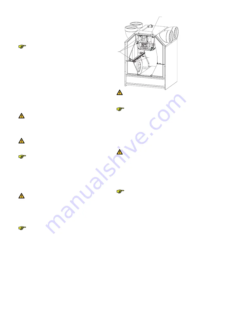
2. Remove the small plastic panel (H) in front of the
control circuit board panel by unscrewing the two
screws.
3. Release the connectors (K) and the earth wire on the
control circuit board panel and fully remove the cables
including the two grommets (K).
4. Remove the entire scroll casing by pressing the
click fasteners (L).
5. Remove the inflow nozzle by pressing the click
fasteners surrounding the scroll casing.
6. Inspecting and if necessary clean the fans.
- Use a soft brush to clean the fan impellers.
- Use a vacuum cleaner to remove dust.
L
K
H
Do not damage the fan impellers or
temperature sensor.
If the preheater element filter also need
maintenance do not re-install the heat
exchanger yet.
7. If no more maintenance is necessary install all
parts in reverse order, reconnect the power and
carry out the self-test in accordance with menu
P76.
Fasten the screws to a maximum of 1.5 Nm.
This is roughly equal to setting 2 of an average
battery-powered drill.
2.9.3 Inspecting and cleaning the
preheater element filter
Clean the filter of the Preheater (if fitted)
once every 4 years.
1. Remove the heat exchanger as instructed in the
maintenance chapter of the heat exchanger.
2. Remove the small plastic panel (I) in front of the
control circuit board panel by unscrewing the two
screws.
3. Release the connectors (J) and the earth wire on
the control circuit board panel and fully remove
the cables including the two grommets (K).
4. Remove the cable (P) from the control circuit
board panel.
5. Remove the base (Q) of the Preheater element.
– The base is fitted in the electronic carriage with
four snap connections. Two snap connections
are located at the front (visible) and two at the
back (not visible).
6. Inspecting and if necessary clean the preheater
element filter.
- Clean the filter with a brush.
- Remove any deposit using a damp cloth.
7. Install all parts in reverse order.
8. Reconnect the power to the ComfoAir.
Summary of Contents for ComfoAir 350
Page 1: ...ComfoAir 350 Installer manual Cooling Fresh Air Clean Air Heating...
Page 4: ...EN 4...
Page 33: ...33 EN...
Page 34: ...EN 34...
Page 35: ...35 EN...


