User’s Manual 1PH HYD3000-HYD6000-ZP1
Rev. 1.0 01/09/2023
Identification: MD-AL-GI-00
Rev. 1.1 of 27/01/2023 - Application: GID
91/193
6.20.
Measurement of exchange through current sensor
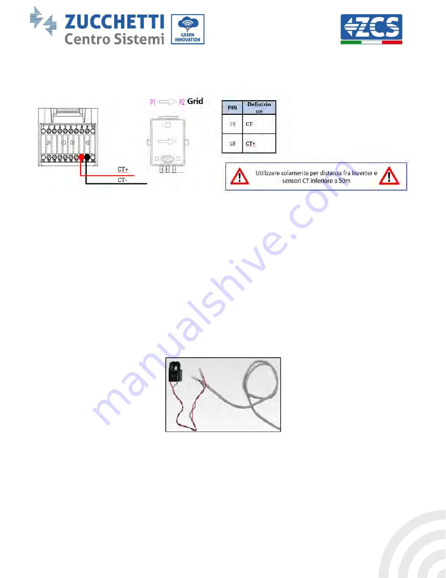
Connect the negative of the sensor to input 19 of the COM connector
Connect the positive of the sensor to input 18 of the COM connector
Correctly position the current sensor, in detail:
CT (measures the current exchanged with the grid). Positioned at the output of the exchange meter so
that all incoming and outgoing power flows can be read, it must include all phase cables entering or
leaving the exchange meter.
The direction of the CT is independent of the installation, and is recognised by the system during the
first start-up.
Use an 8-pin, STP category 6 cable as an EXTENSION CABLE; use all the coloured pins
(blue-orange-green-brown) to extend the positive cable of the CT and all the white/coloured pins
(white/blue-white/orange-white/green/brown) to extend the negative cable of the CT.
The shield must be grounded on one of the two sides. To prevent the cables from breaking, it is recommended
to use a cable with flexible and non-rigid conductors.


