Quick Set-up Guide for the ZB-3062
ZBA Inc.
2
5 Scanning
mode
Scanning output:
You can set the image size to a VGA resolution to accommodate older applications that require a smaller image size. When Image VGA
is set to On, the resultant image is 640x480 pixels. When Image VGA is Off, the image is 752x480 pixels.
Manual/Serial Trigger Mode:
You can activate the imager either by providing an external hardware trigger, or using a serial trigger command
.
When in
manual trigger mode, the imager scans until a bar code is read, or until the hardware trigger is released.
When in serial mode, the imager scans until a bar code has been read or until the deactivate command is sent. In serial mode, the imager can also be set to
turn itself off after a specified time has elapsed (see
Read Time-Out
, which follows).
Manual Trigger, Low Power (
For RS-232 only):
The imager powers down until the trigger is pulled. When the trigger is pulled, the imager powers up and
operates until there is no triggering for the time set with the
Low Power Time-Out
bar code below. There is a delay of up to one second in operation when
the imager is first triggered, but there is no delay when operating in low power time-out mode.
Low Power Time-Out Timer:
Scan the Low Power Time-Out bar code to change the time-out duration (in seconds). Then scan the time-out duration (from 0-
300 seconds) from the inside back cover, and
Save
. Default = 120 seconds. If the unit remains idle during the low power time-out interval, the unit goes into
low power mode. Whenever the trigger is enabled, the low power time-out timer is reset.
Presentation Mode:
This programs the imager to work in Presentation mode. The LEDs are either off or at the lowest power for ambient conditions until a
bar code is presented to the imager. Then the LEDs turn on automatically to read the code. Presentation Mode uses ambient light to detect the bar codes. If
the light level in the room is not high enough, Presentation Mode may not work properly.
VGA Off
*Manual/Serial Trigger
Manual Trigger, Low Power
Presentation Mode
*VGA On
6 Centering
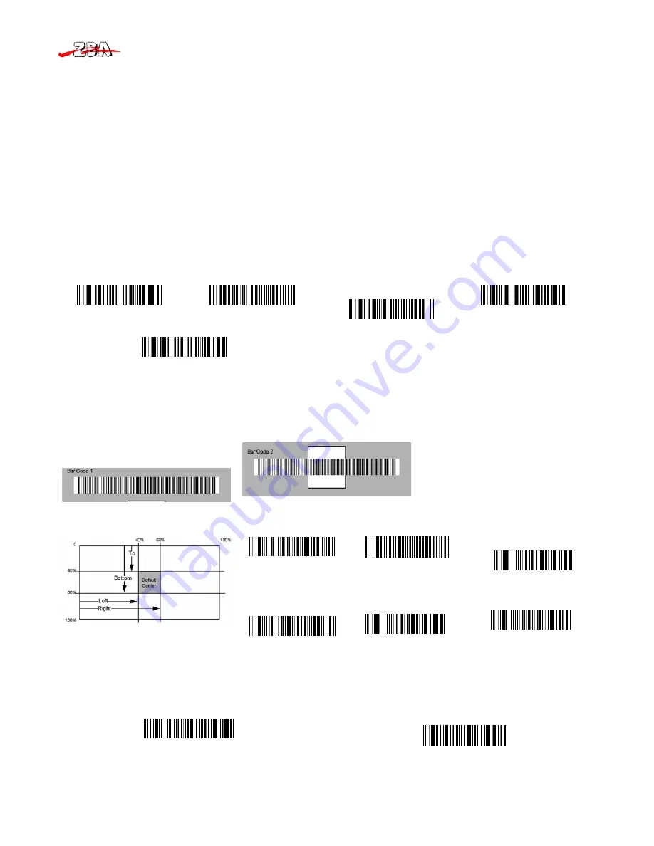
Use Centering to narrow the imager’s field of view to make sure the imager reads only those bar codes intended by the user. For instance, if multiple codes
are placed closely together, centering will insure that only the desired codes are read. (Centering can be used in conjunction with
Aimer Delay
, for the most
error-free operation in applications where multiple codes are spaced closely together. Using the Aimer Delay and Centering features, the imager can emulate
the operation of older systems, such as linear laser bar code imagers. In the example below, the gray area is the full imager field of view and the white area is
the centering window. Bar Code 1 will not be read, while Bar Code 2 will be.
The default centering window is a 128x96 pixel area (640x480 default image size) in the center of the imager’s field of view. The following diagram
illustrates the default top, bottom, left, and right pixel positions, measured from the top and the left side of the imager’s field of view.
*Centering Off
Top of Centering Window
Left of Centering Window
Centering On
Bottom of Centering Window
Right of Centering Window
If a bar code is not within the predefined window, it will not be decoded or output by the imager. If centering is turned on by scanning
Centering On
, the
imager only reads codes that intersect the centering window you specify using the
Top
,
Bottom
,
Left
, or
Right
bar codes. Scan
Centering On
, then scan
one of the following bar codes to change the top, bottom, left, or right of the centering window. Then scan the percent you want to shift the centering
window using digits on the inside back cover of this manual. Scan
Save
. Default Centering = 40% for Top and Left, 60% for Bottom and Right.
All Symbologies On
Standard Product Default Settings


