background image

13

12

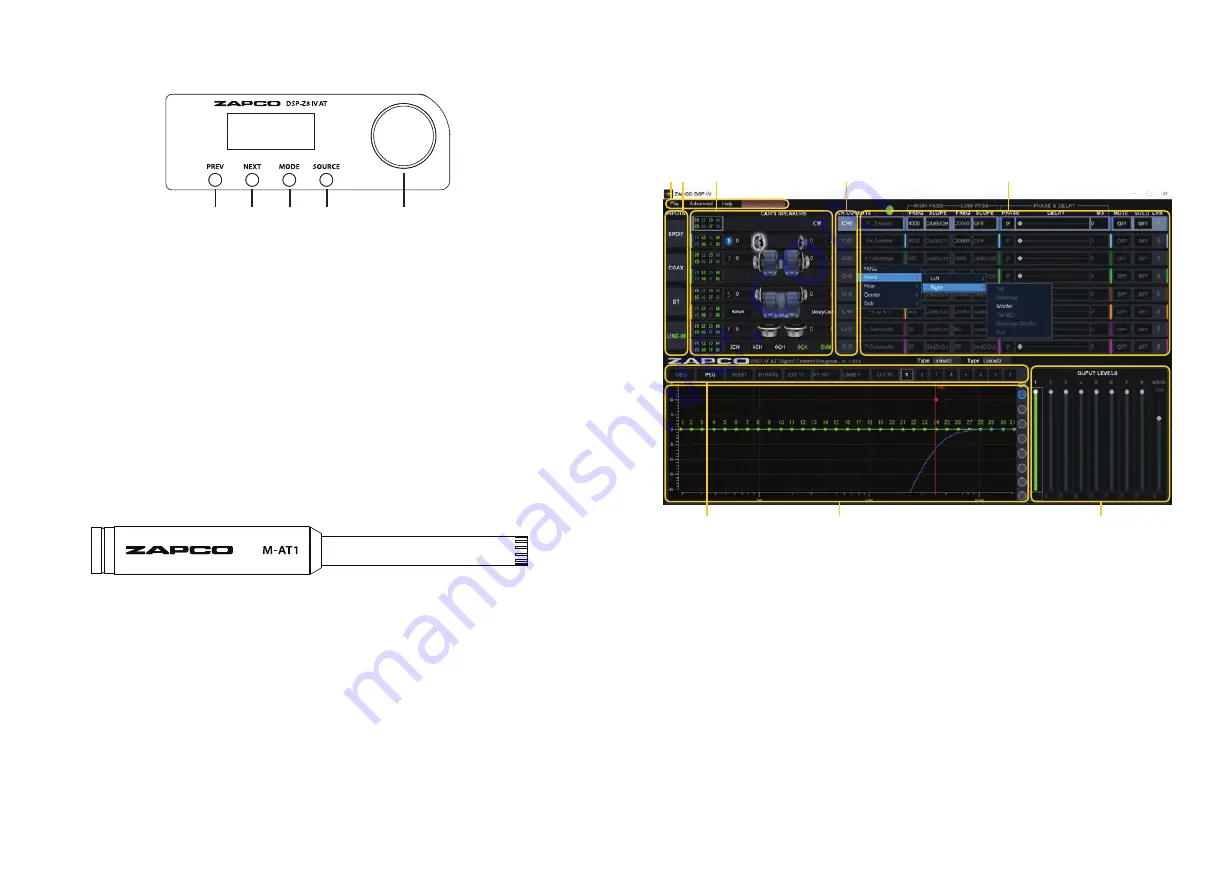
The Graphical User Interface (GUI)

Below is the layout of the control program (GUI) for the DSP AT processors.

Please see the full manual at www.zapco.com/download for a full description of the program,
including the Mixing Set and Auto Calibration in the Advanced menu.

1.

Main Menu for File (Save and Load files and presets), Advanced (Mixing Set and Auto 

Calibration) and Help (Used for updating). 

2.

Input source selection for Line In, Bluetooth (with optional HD-BT module), and both

Optical and Coaxial digital inputs. 

3.

Input quick setup. Choose 2Ch, 4Ch, 6h, or 8Ch, w/ SUM if needed.

4.

Here you choose the channel you want to work on.

5.

System design section for channel function (by drop down menu), crossover, phase,

mute, solo. Here also is channel linking for Crossover, Signal Delay and Output Level 
adjustments.  

6.

EQ Tuning Tools section.

7.

EQ and Crossover graph.

8.

Output level controls by channel or overall, by MAIN.

4

1

7

8

2

Remote Control

The Microphone for Auto Tuning

(optional)

The M-AT1 is a special microphone for setting up the sound automatically, based on 
the response characteristics of the speakers and auto detail detection of the car. After 
detecting all the necessary information, the audio information screen will be transmitted
to the computer.

1.

Connect the microphone to the dedicated port of the unit.

2.

The microphone must be fixed on the headrest of the driving position. This position is 

basically the same as the head of the driver.

1

2

3

4

5

1.

Switch to the previous song (Bluetooth)

2.

Switch to the next song (Bluetooth) 

3.

Mode switching

4.

Source switching

5.

Volume knob. Long press for 5 seconds

enter the switching mode between main
volume or subwoofer. Short press the mute

3

5

6

Summary of Contents for ADSP-Z8 IV-6AT

Page 1: ...Before operating the unit please read this manual throughly and retain it for future reference The complete GUI user s manual is available on zapco com download DSP Z8 IV AT ADSP Z8 IV 6AT Quick Guid...

Page 2: ...l User Interface 13 Technical Specifications 14 Protect your audio investment by using the correct type of wire for Power and Ground See All Wire is not created equal on Page 6 The PC Program GUI for...

Page 3: ...igital signal from your head unit or from a portable HD player The DSP AT units also have a port for HD Bluetooth streaming with the optional HD BT module An interactive digital port will expand your...

Page 4: ...lower price wire is not all copper it is CCA wire CCA stands for Copper Clad Aluminum That means it is aluminum wire with a thin coating of copper around the outside of the wire Does it look like copp...

Page 5: ...nd ADSP Z8 IV 6AT should be set so that when playing the loudest music you will play the clip lights just barely start to flash but never stay on If the clip lights stay on more that just a bare fract...

Page 6: ...peaker output connectors for Ch 3 4 16 Speaker output connectors for Ch 5 6 17 Power Rem Gnd terminals 14 15 16 17 DSP Z8IV AT CH1 CH3 CH5 CH7 CH2 CH4 CH6 CH8 OFF P 4 1 2 3 5 6 1 Comm Port for HD BT m...

Page 7: ...for Crossover Signal Delay and Output Level adjustments 6 EQ Tuning Tools section 7 EQ and Crossover graph 8 Output level controls by channel or overall by MAIN 4 1 7 8 2 Remote Control The Microphone...

Page 8: ...t hearing loss ZAPCO strongly advises that you use common sense when setting volume levels Everything written in this manual is for the proper use of the products Some features or speci cations could...

Page 9: ...1 Modesto California USA Since 1974 zapco com...

Reviews: