Zap LINN LOW DRESSER Assembly Manual Download Page 6

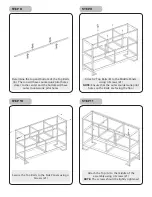
Secure the Top Rails to the Side Panels using 4 

Screws (#1)

Attach the Top (A) to the middle of the 

assembly using 4 Screws (#1) 

NOTE: 

The screws should be lightly tightened

STEP 10

STEP 11

- 4 -

Determine the top and bottom of the Top Rails 

(B). The top will have countersunk pilot holes 

closer to the center and the bottom will have 

outer countersunk pilot holes

STEP 8


Attach 2 Top Rails (B) to the Middle Panels 

using 4 Screws (#1) 

NOTE:

 Ensure that the outer countersunk pilot 

holes on the Rails are facing the floor

STEP 9

Summary of Contents for LINN LOW DRESSER

Page 1: ...1...

Page 2: ...COMPONENTS A B C D L E F G H I x1 x2 x2 x2 x1 x3 x3 x2 x2 x5...

Page 3: ...s D The top of the rails will have a smooth pilot hole while the bottom of the rails will have a countersunk pilot hole pilot hole with a circular cavity designed to seat the cone shaped head of the s...

Page 4: ...enter and the bottom will have 2 outer countersunk pilot holes NOTE Ensure that the back metal plates on the Middle Panel face the same way as the back metal plates on the rear side of the Side Panels...

Page 5: ...le Rails using 4 Screws 2 Secure the Middle Rails to the Side Panels using 4 Screws 1 STEP 6 NOTE Ensure that the back metal plates on the Middle Panels face the same way as the back metal plates on t...

Page 6: ...y tightened STEP 10 STEP 11 4 Determine the top and bottom of the Top Rails B The top will have countersunk pilot holes closer to the center and the bottom will have outer countersunk pilot holes STEP...

Page 7: ...tly tightened Tighten all 6 Screws STEP 12 STEP 13 5 Attach the two Brace Bars L at the center using 1 Hex Bolt 4 and 1 Capped Nut 4 Attach the Brace Bars to the assembly using 4 Screws 3 and 4 Capped...

Page 8: ...6 Insert a Bin Bottom H I into each corresponding Bin H I for a total of 5 bins Attach 1 Handle G to each Bin using 2 Handle Screws STEP 16 STEP 17 Slide each Bin into place in the assembly STEP 18...

Page 9: ...d level the unit if the floor is uneven Turn the Adjustable Screws at the base of the Side Panels to level the assembly NOTE Adjust the rear Adjustable Screws first and if the wobble persists adjust t...

Reviews: