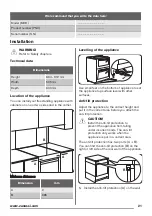
Make sure that the wall is made of a solid
material. If not, you need to make the wall
sufficiently strong to hold the weight.
Make sure that the surface behind the
appliance is smooth.
2. Put the appliance in the middle of the space
between the cupboards.
If the space is larger than the width of the
appliance, you must adjust the side
measurement.
3. Install the anti-tilt protection (A)
approximately 77 mm below the top surface
of the appliance and 50 mm from the left or
right side of the appliance into the circular
hole on the bracket. Screw it into the wall.
50 mm
77 mm
A
4. Check that the anti-tilt protection (A) fits
minimum 20 mm into the hole in the rear
wall of the appliance (B) when you push the
appliance.
Other technical data
WARNING!
These instructions are only valid in
the countries whose symbols appear
on this booklet's cover.
Gas cate-
gory:
I2H
Gas supply G20 (2H) 20 mbar
Gas burners
BURNER
NORMAL POWER
kW
Natural Gas
INJECTOR MARK 1/100 mm
Btu/h
Auxiliary
1
70
3412
Semi-rapid
1.9
96
6483
Rapid
3
119
10236
Gas Connection
Use a flexible pipe in compliance with the
regulation in force. Make sure they do not come
in touch with mobile parts and are not
squeezed.
WARNING!
Only a qualified and competent
person can do the gas installation.
Before you connect te gas,
disconnect the appliance from the
electricity supply or switch off the
fuse in the fuse box. Close the
primary valve of the gas supply.
Supply piping should not be less
than R3/8. Connection is made to
the Rc 1/2 (1/2 “ B.S.P.) female
threaded. The entry pipe is located
just below the hob level on the rear
left hand side of the appliance.
The gas supply ramp is on the rear
side of the appliance.
WARNING!
Only liquid sealants can be used
when the inlet gas pipe is fitted i.e.:
do not use the P.T.F.E. sealant tape.
When the installation is complete,
carry out a gas tightness test and
make sure that the seal of each pipe
fitting does not leak.
22
www.zanussi.com


