background image

61

INSTALLATION

Location

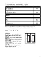
The appliance should be installed well away from
sources of heat such as radiators, boilers, direct
sunlight etc. 

For safety reasons, minimum ventilation must be as
shown in Fig.

Appliance positioned under overhanging kitchen wall
units (see Fig. A).

Appliance positioned without overhanging kitchen
wall units (see Fig. B).

Attention: keep ventilation openings clear of
obstruction.

Two adjustable feet at the cabinet base allow
accurate levelling of the appliance.

NP00

100 mm

15 mm

15 mm

A

B

TECHNICAL INFORMATION

Energy Efficiency class

B

250

77

1,20

438

14

20

2000

600

600

640

1210

Net Fridge Capacity lt.

Energy Consumption kWh/24h

Energy Consumption kWh/year

Freezing Capacity kg

Rising time h

Net Frezer Capacity lt.

Dimensions mm

High

Width

Depth

Widthwith opened doors

Depth with opened doors

The technical infomation are situated in the rating plate on the internal left side of the appliance .

Summary of Contents for ZA 3 PS

Page 1: ...KÜHL GEFRIERSCHRANK REFRIGERATEUR CONGELATEUR TWEEDEURS KOELKAST FRIDGE FREEZER ZA 3 PS BEDIENUNGSANLEITUNG MODE D EMPLOI GEBRUIKSAANWIJZING INSTRUCTIONBOOKLET 2222 089 11 ...

Page 2: ...e of refrigerating appliances unless they are approved for this purpose by the manufacturer Service Repair Any electrical work required to install this appliance should be carried out by a qualified electrician or competent person This product should be serviced by an authorized Service Centre and only genuine spare parts should be used Under no circumstances should you attempt to repair the appli...

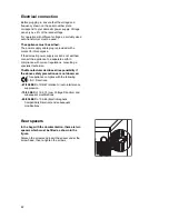
Page 3: ...k of the product should be against a wall If the appliance has been transported horizontally it is possible that the oil contained in the compressor flows in the refrigerant circuit It is advisable to wait at least two hours before connecting the appliance to allow the oil to flow back in the compressor Environment Protection This appliance does not contain gasses which could damage the ozone laye...

Page 4: ...ith the drill see figure For masonry walls 4 Insert the 4 metal bushings and tighten the screws 5 Fasten the brackets horizontally in the lower set of holes as illustrated in the figure after having previously removed the screws 6 Push the appliance towards the wall and turn the brackets downwards 90 Make sure that the lower part of the brackets is located between the appliance and the plate 7 Ins...

Page 5: ...ards higher settings However the exact setting should be chosen keeping in mind that the temperature inside the refrigerator depends on room temperature how often the door is opened the quantity of food stored location of appliance A medium setting is generally the most suitable To stop operation simply turn the thermostat knob to position ÇOÈ Important If the ambient temperature is high or the ap...

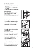
Page 6: ... or wrap the food particularly if it has a strong flavour Position food so that air can circulate freely round it 3P002 A 3P001C Use of the adjustable temperature compartment Temperature adjustment The temperature can be adjusted either with the thermostat see refrigerator temperature adjustment or by means of the flaps air inlets located in the refrigerator compartment When the flaps A are closed...

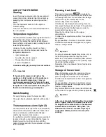
Page 7: ...It will remain lit up until the optimum temperature for the conservation of frozen food is attained Storage of frozen food When first starting up or after a period out of use before putting the products in the compartment press the Super knob at least 12 hours before To obtain the best performance from this appliance you should if large quantities of food are to be stored remove all drawers and ba...

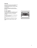
Page 8: ...this case cooking will take longer Ice tray support The ice tray support with the supplied trays must be hooked to the front drawer or crisp of the freezer compartment Any other use can prejudice its functioning The ice trays are to be filled 3 4 with drinking water and placed in the support Do not use metal tools or utensils to remove the trays Never eat popsicles or ice cubes as soon as they are...

Page 9: ...ration Useful hints Meat all types wrap in polythene bags and place on the glass shelf above the vegetable drawer For safety store in this way only one or two days at the most Cooked foods cold dishes etc these should be covered and may be placed on any shelf Fruit and vegetables these should be thoroughly cleaned and placed in the special drawer s provided Butter and cheese these should be placed...

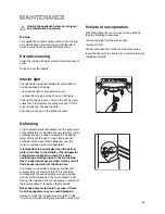
Page 10: ...already inserted into the drain hole The freezer compartment however will become progressively covered with frost This should be removed with the special plastic scraper provided whenever the thickness of the frost exceeds 4 mm During this operation it is not necessary to switch off the power supply or to remove the foodstuffs Never use sharp metal tools to scrape off frost from the evaporator as ...

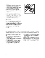
Page 11: ...means to speed up the thawing process other than those recommended by the manufacturer A temperature rise of the frozen food packs during defrosting may shorten their safe storage life CUSTOMER SERVICE AND SPARE PARTS If the appliance is not functioning properly check that the plug is firmly in the wall socket and the mains power switch is on there is an electricity supply find out by plugging in ...

Page 12: ...ntilation openings clear of obstruction Two adjustable feet at the cabinet base allow accurate levelling of the appliance NP00 100 mm 15 mm 15 mm A B TECHNICAL INFORMATION Energy Efficiency class B 250 77 1 20 438 14 20 2000 600 600 640 1210 Net Fridge Capacity lt Energy Consumption kWh 24h Energy Consumption kWh year Freezing Capacity kg Rising time h Net Frezer Capacity lt Dimensions mm High Wid...

Page 13: ...ate earth in compliance with current regulations consulting a specialist technician The Manufacturer declines all responsibility if the above safety precautions are not observed This appliance complies with the following E E C Directives 87 308 EEC of 2 6 87 relative to radio interference suppression 73 23 EEC of 19 2 73 Low Voltage Directive and subsequent modifications 89 336 EEC of 3 5 89 Elect...

Page 14: ... hinge on the other side 7 Mount the lower door 8 Remove the pin of the lower hinge and mount it on the other side 9 Mount the lower hinge E on the other side insert the hole cap G remove hole cap F from the aeration grid D by pressing it in the direction indicated by the arrow and mount it on the other side 10 Mount the aeration grid D again by snapping it into place 11 Remove the three screws of...

Page 15: ...inner holes 19 Close the door and tighten the third screw in the hole 20 Unscrew the handles Mount them again on the opposite side after having punctured the caps with a punch Cover the holes left free with the caps supplied in the bag Door fastener Your appliance is equipped with a door fastener in the lower part of the upper door to assure the proper closing of the door D737 ...

Reviews: