
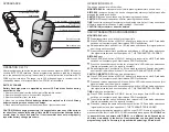
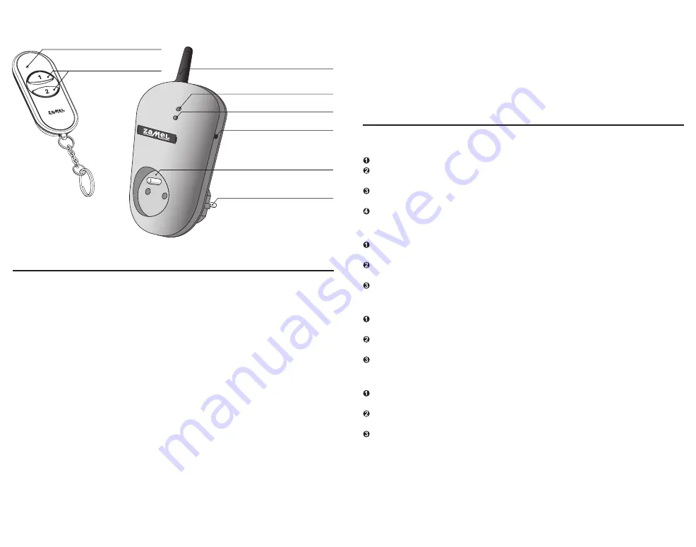
APPEARANCE
OPERATION P-257/2
After pressing the push-button the remote control sends a signal on 868,32 MHz which
controls EXTA FREE receivers. Device programming procedure (adding a transmit-
ter to the transmitter’s memory) is described in manual instruction of particular EXTA
FREE system receivers. The range (up to 250 m depending on a receiver) can be
changed by means of a retransmitter or few RTN-01 retransmitters.
BATTERY CHANGE
Battery discharge status is signalled by several LED red diode flashes during
transmission time.
1. Remove the screws from the bottom part of the remote control.
2. Remove the upper cover with the silicon keyboard.
3. Remove the battery from the latch.
4. Mount a new battery.
Watch battery polarisation marked on the latch. Wrong
battery mounting may cause device damage.
5. Place back the top cover with the keyboard and tighten the screws.
CAUTION: While changing the battery, it is suggested to press any of the buttons
for about 5 seconds before putting it into a latch. Next press transmission button
several times to check its operation. If the transmitter does not work properly
repeat the battery change procedure.
RADIO TRANSMITTERS PROGRAMMING
OPERATION RWG-01
MONOSTABLE
mode:
Press transmitter’s push-button for a longer time.
Press PROG push-button of RWG-01 device for a longer time until LED red diode
switches on (constant signal). Next release PROG push-button.
Release transmitter’s push-button. LED red diode switches on (first signal pulsates,
next the signal is constant).
Press the same transmitter’s push-button and release it. LED red diode switches on
(the signal pulsates) and next it switches off - THE TRANSMITTER IS ADDED.
BISTABLE
mode:
Press PROG push-button of RWG-01 device for a longer time until LED red diode
switches on (constant signal). Next release PROG push-button.
Press the transmitter’s push-button for a longer time. LED red diode switches on
(first signal pulsates, next the signal is constant).
Release transmitter’s push-button. LED red diode switches on (the signal pulsates),
next the LED red diode switches off - it means the TRANSMITTER IS ADDED.
SWITCH ON/SWITCH OFF
mode (two push-buttons):
Press PROG push-button of RWG-01 device for a longer time until LED red diode
switches on (constant signal). Next release PROG push-button.
Press and release transmitter’s first push-button. LED red diode switches on (first
signal pulsates, next the signal is constant).
Press and release the second transmitter’s push-button. LED red diode switches on
(the signal pulsates) and next it switches off - THE TRANSMITTER IS ADDED.
TIME
mode (one push-button):
Press PROG push-button of RWG-01 device for a longer time till LED red diode
switches on (constant signal). Next release PROG push-button.
Press the transmitter’s push-button and then release it. LED red diode switches on
(first signal pulsates, next the signal is constant).
Press and release the same transmitter’s push-button. LED red diode switches on
(signal pulsates) and then switches off - THE TRANSMITTER IS ADDED.
An exemplary programming procedure with the use of P-257/2 remote controller. The
procedure for the rest of radio EXTA FREE transmitters is analogous.
CAUTION: Eve-
ry transmitter can cooperate with RWG-01 in a different mode, depending on
how they were added to the device. One transmitter can be added during one
programming cycle. Full memory is signalled with pulsating LED red diode.
The device can operate in five modes:
MONOSTABLE
the relay operates only while pressing transmitter’s push-button.
BISTABLE
(one push-button) the device changes relay status cyclically always after
pressing the same push-button.
SWITCH ON
the device switches on after pressing the push-button.
SWITCH OFF
the device switches off after pressing the push-button.
TIME
the device switches off according to the adjusted time (tp), but it may be switched
off before adjusted time finishes. Default settings - 15 seconds.
CAUTION! Adjusted time cannot be deleted.
Antenna
Optic signalling
of transmitters’ switching on
Programming push-button
Receiver’s socket
Power supply plug
Optic signalling of input voltage
Optic signalling
of transmitter’s operation
Push-buttons


