background image

10

The design and specifications of this product may change without prior notice to enhance its quality.

HD160XT Plus

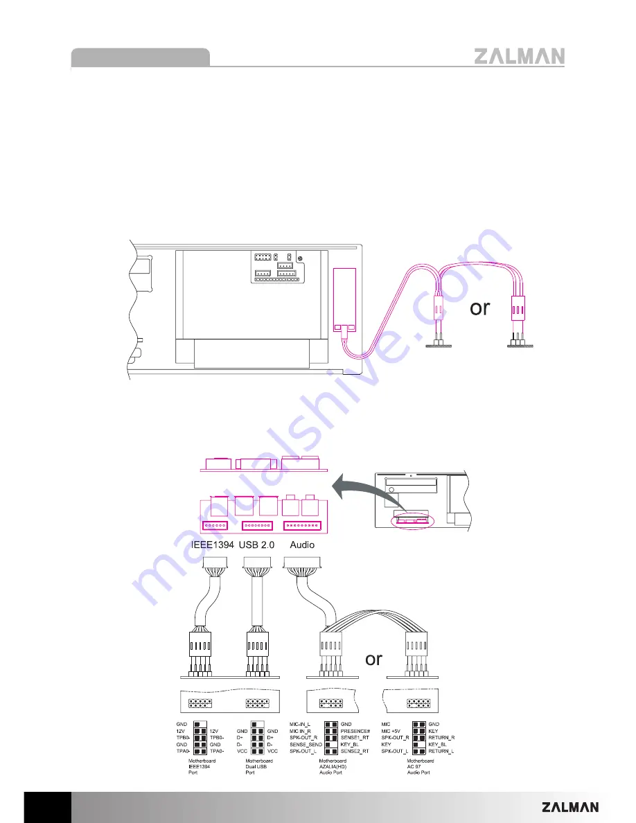
(5) Connecting the Cables

1) Power and Data Transmission Cables

Connect the Power and Data Transmission Cables (IDE or SATA) required for the HDD,

ODD, FDD, VGA etc.

2) Power LED Cable

Connect the Power LED Cable (2-Pin or 3-Pin) to the motherboard’s Front Panel Port

(refer to the motherboard’s manual).

3) Front I/O Cable

Connect the USB Cable, IEEE1394(FireWire) Cable, and Audio Cable to the

motherboard (Refer to the motherboard’s manual). 

P

Po

ow

we

err L

LE

ED

D C

Ca

ab

blle

e

M

Mo

otth

he

errb

bo

oa

arrd

d

F

Frro

on

ntt P

Pa

an

ne

ell P

Po

orrttss

Summary of Contents for HD160XT Plus

Page 1: ...enhance its quality www zalman co kr www zalmanusa com English version Please read this manual thoroughly before installation Please visit our website and watch the HD160XT Plus installation video to...

Page 2: ...s world of silent computing The HD160XT Plus is designed for ultra quiet home theatre PC operation utilizing optimized ventilation and anti vibration reinforcements making it ideal for environments th...

Page 3: ...des of the unit must not be blocked 5 Keep this unit away from heat sources and direct sunlight as well as from water oil and humidity Place the unit on a flat leveled solid and well ventilated area 6...

Page 4: ...0XT Plus Main Components 2 Case Parts 3 iMON Parts HDD Chassis Top Panel ODD Chassis Main Chassis 20 HDD Bolts PH 6 32X10 4 Power Supply Bolts PH 6 32X6 18 ODD Motherboard Bolts PWH M3X5 2 micro ATX S...

Page 5: ...Standard ATX ATX12V PCI AGP Card Compatibility Full Size Drive Bays 5 X 3 5 Internal Drive Bays 1 X 5 25 External Drive Bay Cooling Components Rear Panel 2 X 80mm Exhaust Fans Bottom Panel 1 X 80mm Ex...

Page 6: ...anel Buttons I O Ports Remote Control Receiver System Power Indicator Power Button iMON Control Buttons AUDIO Headphones Mic Port IEEE1394 FireWire Port USB Port Card Reader Slot MS Pro Duo CF Micro D...

Page 7: ...g the Enclosure To remove the Top Panel of the enclosure unscrew the six Bolts FH M3x6 2 Removing the ODD and HDD Chassis Remove the Bolts PWH M4x5 and horizontally pull the ODD and HDD Chassis approx...

Page 8: ...ply Mount the motherboard and power supply by using appropriate bolts Mount the computer components CPU VGA RAM etc onto the motherboard To mount a microATX motherboard first install the two enclosed...

Page 9: ...D Chassis onto the enclosure s Front Panel and Side Panel then secure them onto the panels with the Fixing Bolts PWH M4x5 This product is provided with one 5 25 bay and five 3 5 bays For optimal HDD c...

Page 10: ...SATA required for the HDD ODD FDD VGA etc 2 Power LED Cable Connect the Power LED Cable 2 Pin or 3 Pin to the motherboard s Front Panel Port refer to the motherboard s manual 3 Front I O Cable Connect...

Page 11: ...Connect the System Power Switch Cable 2 Pin with the motherboard s Front Panel Port Refer to the motherboard manual Connect the Standby Power Cable 20 Pin or 24 Pin to the motherboard and power supply...

Page 12: ...zel 3 Remove the Tape Film on the back side of the Aluminum ODD Bezel and stick the Aluminum ODD Bezel onto the ODD Tray 7 7 I In ns st ta al ll li in ng g t th he e M Mu ul lt ti im me ed di ia a S S...

Page 13: ...ention to make sure that the air vents and intake exhaust fans are not blocked by the cables Placement of this system on a well ventilated area good intake of cold air and release of hot air allows ef...

Page 14: ...that is either equipped with an Ultra Quiet VGA cooler or is capable of being equipped with an Ultra Quiet VGA cooler VGA Cooler Ultra Quiet VGA Cooler Power Supply Power Supply equipped with a 120mm...

Reviews: