2017
Ytec3D.com Written by: Yvo de Haas Latest version: 07-01-2017
[
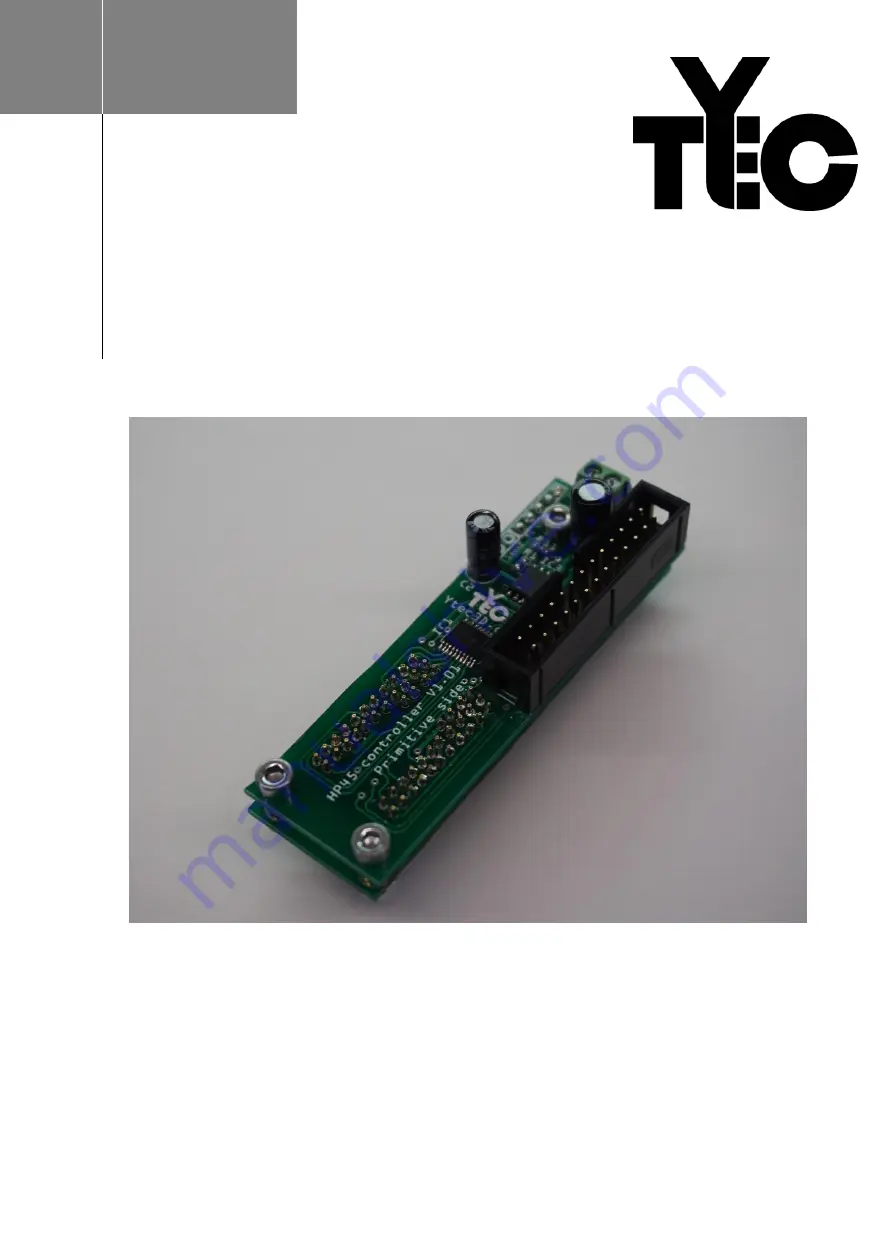
HP45 CONTROLLER V1.01 ASSEMBLY
]
How to assemble the HP45 controller V1.01 and printhead carrier
All manuals and user guides at all-guides.com
all-guides.com
Page 1: ...Written by Yvo de Haas Latest version 07 01 2017 HP45 CONTROLLER V1 01 ASSEMBLY How to assemble the HP45 controller V1 01 and printhead carrier All manuals and user guides at all guides com a l l g u...
Page 2: ...assembly guide Ytec3d com Page 2 Table of Contents Introduction 3 PCB assembly 4 Before you start 4 Tools required 4 Bill of materials 5 Assembly 11 Appendix 1 Schematics 17 All manuals and user guid...
Page 3: ...e simplest kit to assemble with a few hours and some experience in SMD soldering it should be possible to assemble How to operate the HP45 controller after assembly is described in a different manual...
Page 4: ...soldering SMD components If you are not completely sure about your soldering skills this controller might be too difficult Tools required To assemble the HP45 controller you will need the following t...
Page 5: ...le 151785406493 hash item23571d801d g iAkAAOS wIgNXl3Mt Note Round head buy more in case there are damaged pins Name TLC59213 Quantity 2 Part number 595 TLC59213AIPWR Package TSSOP 20 Supplier Mouser...
Page 6: ...EF4017BT652 qs sGAEpiMZZM utXGli8Ay4kDE4J8KCiPsFLWWSlq0qOaw 3d Note Name HCF4081 Quantity 1 Part number 511 4081BM TR Package SOP 14 Supplier Mouser Link http mouser com ProductDetail STMicroelectroni...
Page 7: ...om ProductDetail Panasonic ERJ 3EKF1201V qs sGAEpiMZZMu61qfTUdNhG6gKAQ VNBKOoTC0hNDHH3WI 3d Note Name 2 2k resistor 0 1W Quantity 6 Part number 667 ERJ PA3F2201V Package 0603 Supplier Mouser Link http...
Page 8: ...AEpiMZZMtZ1n0r9vR22fP Wwtj8kO8aGTdhkAsuCM5vYvIsVJPtRg 3d 3d Note Voltages as low as 16V permitted Name 100 F 16V electrolytic capacitor Quantity 1 Part number 667 ECA 1CM101I Package 5x11mm Supplier M...
Page 9: ...er Mouser Link http mouser com ProductDetail Phoenix Contact 1984617 qs sGAEpiMZZMvZTcaMAxB2AE SRb0B7PLuENBlLLdAoFxM 3d Note Name standoff 5mm for M3 Quantity 3 Part number 855 R30 6200514 Package Sup...
Page 10: ...ty 3 Part number Package Supplier Link Note Temporarily used to hold the controller together Name Pin template Quantity 1 Part number Package Supplier Ytec3d Link Note Optional 3d printed Used for mou...
Page 11: ...he primtive and address side text facing up Down or back is the opposing side Note in future versions the boards will come in 2 pre cut sections The first batch does not have this 2 Solder the TLC5921...
Page 12: ...de with the markings as shown in the image 7 Solder the 4081 IC8 on the front of the address side with the marking as shown in the image 8 Solder the DMG2302UK 7 Q1 Q2 or a similar mosfets on the fron...
Page 13: ...the 2 2k resistor R1 on the front of the primitive side 14 Solder 5x 2 2k resistor R6 R7 R8 R9 R10 on the front of the address side 15 Solder the 5 pin header in the front of the address side Cut wire...
Page 14: ...back side Make sure there are no shorts or unconnected pins Once the 2 boards are fully soldered together they are not going to come apart again without some serious work With this check the TLC59213...
Page 15: ...the 52 holes It is advised to check if every pin springs before mounting it After all pins are placed all pins should roughly stick the same length out of the primitive front side board about 2 3mm 2...
Page 16: ...he address side making sure no solder leaks into the joint between the static part and the sprung part of the pogo pin 26 Solder the primitive front side of the 5 pin header and cut the wire flush wit...
Page 17: ...Appendix 1 Schematics All manuals and user guides at all guides com...