background image

http://www.yowzafitness.com/ 

33 


COMPUTER OPERATION 


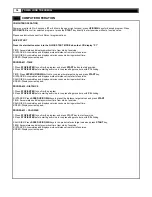
 START 

 Press to start exercise initial speed 0.5 ml/0.8 km. 
 

 STOP / ENTER                   

1. Press to confirm program and preset function values under setting mode. 
2. Press to quit preset program and function value after complete single program. 
3. Setting procedure: returns to beginning of setting mode before pressing the START key. 
4. Press to stop exercise during workout time. 


 SPEED UP / DOWN BUTTON                                                        

 1.  Press to increase/decrease exercise speed by 0.1ml /km. 
 2. Hold the button to increase/decrease rapid speed by 0.5ml/km per second and release the button to stop the function. 
 Press to select programs and preset related function value. 


INCLINE UP/DOWN BUTTON 


1.  Press to increase/decrease incline level. 


2.  Hold the button to increase/decrease incline level per second and release the button to stop the function. 


 EXPRESS SPEED BUTTON 


Press the quick speed button to select the target speed.  


 EXPRESS INCLINE BUTTON 


Press the quick incline button to select the target incline. 


MODE BUTTON 


Please MODE button the exchange the display   


 IMPORTANT 

· The console display will turn itself off automatically about five minutes after the bell has stopped moving. 
· The pulse function is for reference only, and not to be used for medical purposes. 
 

 SAFETY KEY 

 
 The safety key must be inserted into the slot on the console in order to operate the treadmill. Always insert the safety key and attach   
 the clip to your clothing waist before beginning your workout. 
 
 If you should encounter problems and need to stop the motor quickly, simply pull on the cord the disengage the safety key from the   
 console. To continue operation simply turn the power switch to off, set the speed controller to stop and then reinsert the safety key  
 into the console. 
 

Summary of Contents for JUNO

Page 1: ...ONS P12 P15 7 EXPLODED DIAGRAM P16 P22 8 STABILIZER ADJUSTMENT P23 10 MAINTAINENCE P24 P25 11 IMPORTANT STEPS P26 12 MUSCLE CHART P27 13 STRETCHING ROUTINE P28 14 TROUBLESHOOTING P29 15 WARRANTY P30 P31 16 COMPUTER OPERATION P32 P37 Yowza Technical Support 877 969 9240 Serial Number ________________________ Original Sales Order ________________________ Purchase Date ______________ ...

Page 2: ...ll Athletic support clothes are recommended for both men and women Always wear athletic shoes Never use the treadmill with bare feet wearing only stockings or in sandals When connecting the power cord plug the power cord into a grounded circuit No other appliance should be on the same circuit Always straddle the belt and allow it to start moving before stepping onto the belt Always examine your tr...

Page 3: ...res The manufacturer recommends a single outlet surge protector with a UL 1449 rating as a Transient Voltage Surge Suppressor TVSS with a UL suppressed voltage rating of 400V or less and an electrical rating 110VAC 15 amps This treadmill must be grounded to reduce the risk of electrical shock Grounding provides a path of least resistance for electric current should the treadmill malfunction This t...

Page 4: ...e a friend Some of the assembly steps may require heavy lifting It is recommended that you obtain the assistance of another person when assembling this product User Weight Limitation Please note that there is a weight limitation for this product If you weigh more than 300LBS Approx 135 Kgs It is not recommended that you use this product Serious injury may occur if the user s weight exceeds the lim...

Page 5: ...tion Qty 220 106 111 201 202 204 203 A1 A3 A2 A4 D C A1 Console Assembly 1 A2 Main Frame Assembly 1 A3 Right Handlebar Assembly 1 A4 Left Handlebar Assembly 1 111 Safety Key 1 106 Water Bottle Holder 1 201 Upright Cover LL 1 202 Upright Cover LR 1 203 Upright Cover RR 1 204 Upright Cover RL 1 220 Side Cover 2 C Power Cord 1 D Lubricant 1 ...

Page 6: ...help distinguish between the various types of screws and bolts use the scale below to measure them and compare them to the sizes listed No Description Qty 901 904 905 B A E 901 M8x40mm Allen Head Bolt 4 904 M10x62mm Bolt 4 905 3x12mm Screw Cone Pivot 4 A 6mm Allen Key 1 B 5mm Allen Key 1 E Screwdriver 1 MILLIMETERS ...

Page 7: ...14 Handlebar Foam Grip 2 JUNO 214 215 Left Handlebar 1 JUNO 215 216 Handlebar End Cap 2 JUNO 216 218 Left Upright 1 JUNO 218 219 Right Upright 1 JUNO 219 220 Side Cover 2 JUNO 220 221 Upright Lower Cover LL 1 JUNO 221 222 Upright Pivot Bracket Left 1 JUNO 222 223 Upright Lower Cover LR 1 JUNO 223 224 Upright Lower Cover RL 1 JUNO 224 225 Upright Pivot Bracket Right 1 JUNO 225 226 Upright Lower Cov...

Page 8: ...rd Connection Wire 1 JUNO 609 610 MP3 Insert Wire 1 JUNO 610 611 Elevation Control Board Fix Bolt 6 JUNO 611 612 Power Insert 1 JUNO 612 613 8pin Power Wire Upper 1 JUNO 613 614 8pin Power Wire Middle 1 JUNO 614 615 8pin Power Wire Lower 1 JUNO 615 616 3C Power Wire 1 JUNO 616 617 MP3 Connection Wire 1 JUNO 617 618 3P Power Connection Wire 1 JUNO 618 619 1pin Power Connection Wire 1 JUNO 619 622 H...

Page 9: ...NO 809 820 6 5x13x1 5mm Washer 7 JUNO 820 822 Handlebar End Cap Holder 2 JUNO 822 823 6x11x3mm Washer 2 JUNO 823 824 M6x30mm Allen Head Bolt 2 JUNO 824 831 25mm C Clip 2 JUNO 831 833 Bushing 24 85x32 35x16mm 4 JUNO 833 835 M10x62mm Bolt 1 JUNO 835 841 4x12mm Plastic Screw 6 JUNO 841 861 8x22x2mm Washer 6 JUNO 861 863 M10x50mm Allen Head Bolt 2 JUNO 863 865 M10 Nylon Nut 5 JUNO 865 866 M8 Nylon Nut...

Page 10: ...O 885 890 M6x10mm Screw 2 JUNO 890 891 15x22x1mm Washer 7 JUNO 891 892 M6x70mm Allen Head CAP Bolt 3 JUNO 892 895 M8x20mm Allen Head CAP Bolt 4 JUNO 893 897 5x10mm Screw 2 JUNO 897 898 3x8mm Screw Cone Point 8 JUNO 898 JUNO 900 901 M8x40mm Allen Head Bolt 4 JUNO 901 904 M10x62mm Bolt 4 JUNO 904 905 3x12mm Screw Cone Pivot 4 JUNO 905 ...

Page 11: ...220 904 904 220 219 219 218 219 219 A STEP1 A Rotate the Uprights 118 119 up to vertical position STEP1 B Using the two M10x62mm Bolts 904 to secure the upright to frame STEP1 C Attach the Side Cover 220 to the frame 904 X4 220 X2 STEP1 A STEP1 B STEP1 C ...

Page 12: ...Power Wire Upper 613 to 8pin Power Wire Middle 614 and Safety Key Wire Upper 628 to Safety Key Wire Middle 629 STEP2 B Attach the Console Support Tube to the Upright and Attach the Handlebar A3 A4 to the Console Support Tube STEP2 C Using the Allen Head Bolt 901 to secure the Handlebar and Console Support Tube to the Upright 901 X4 STEP2 A STEP2 B STEP2 C ...

Page 13: ...13 STEP3 ASSEMBLY 905 201 215 218 905 202 203 205 219 204 218 202 201 E STEP3 Attach the Upright Cover 201 202 to the Left Upright tube and secure using the Cone Point Screw 905 Repeat the above process for the Right side 905 X4 ...

Page 14: ...14 YOWZA JUNO TREADMILL STEP4 ASSEMBLY 106 104 STEP4 Attach the water bottle holder 106 to the left side console Your treadmill is now fully assembled 106 X1 ...

Page 15: ...ww yowzafitness com 15 801 898 802 802 802 106 898 898 102 104 103 110 105 108 107 112 809 802 802 802 809 115 901 214 215 822 823 216 824 820 901 205 822 823 820 824 216 214 803 803 632 632 EXPLODED DIAGRAM ...

Page 16: ...YOWZA JUNO TREADMILL 801 898 802 802 802 106 898 898 102 104 103 110 105 108 107 112 809 802 802 802 809 115 901 214 215 822 823 216 824 820 901 205 822 823 820 824 216 214 803 803 632 632 EXPLODED DIAGRAM ...

Page 17: ...http www yowzafitness com 17 807 865C 806 833 833 223 224 218 219 222 904 221 806 220 831 225 807 904 831 226 806 220 865C 905 202 201 203 204 EXPLODED DIAGRAM ...

Page 18: ...18 YOWZA JUNO TREADMILL 868 402 404 404 403 868 867 401 401 401 401 869 407 871 870 406 870 870 405 401 841 408 408 841 867 401 401 401 401 401 EXPLODED DIAGRAM ...

Page 19: ...873 507865 508 509 510 875 874 895 872 510 612 801 509 868 505 511 514 604 868 884 868 868883 884 883 868 883 517 868 606 515 897 605 513 878 865 870 880 866 877 861 876 879 516 625 868 602 868 868 611 601 603 624 512 861C 895 861C 870C 870C 884 884 883 883 898 898 716 EXPLODED DIAGRAM ...

Page 20: ...20 YOWZA JUNO TREADMILL 705 703 702 820 892 885 701 704 891 624 885 705 891 704 868 625 868 708 707 710 709 890 863 705 891 865 722 709 863 722 891 865 714 715 705 704 820 892 868 841 719 WIRE DIAGRAM ...

Page 21: ...http www yowzafitness com 21 628 613 632 632 623 608 640 622 636 622 613 614 614 615 630 629 629 628 622 630 605 606 612 615 603 601 607 604 602 616 618 609 634 610 617 619 ...

Page 22: ...ake sure the treadmill stabilizer is adjusted correctly prior to use You may need the assistance of another person to perform this adjustment First locate the two adjustable stabilizers under the base frame Then simply rotate them in or out to adjust the level of the treadmill When properly adjusted the treadmill should sit firmly on both stabilizers and all cushions Locate the two adjustable stab...

Page 23: ...ocedure until the walking belt is centered It may be necessary to set walking belt tension once you have completed this procedure if the belt feels like it is slipping while walking Refer below to the Walking belt slipping instructions Walking belt has shifted to the right First unplug the power cord from the surge protector Using the hex key provided turn the right rear roller adjustment bolt 1 4...

Page 24: ...ed periodically for lubrication to ensure optimal treadmill performance Your treadmill should not have to be lubricated usually within the first 400 hours of use Every 2 months of operation lift the sides of the walking belt and feel the top surface of the running deck as far as you can reach If you feel signs of silicone no further lubrication is required If it feels dry to the touch follow the i...

Page 25: ... to exercise only for a few minutes in your target zone However your aerobic fitness will improve over the next six to eight weeks Don t be discouraged if it takes longer It s important to work at your own pace Ultimately you ll be able to exercise continuously for 30 minutes And the better your aerobic fitness the harder you will have to work to stay in your target zone But remember these essenti...

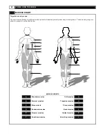
Page 26: ... primarily lower body muscle groups These muscle groups are shown in gray color on the chart below MUSCLE GROUPS A Shoulder muscles Calf muscles G B Pectoral muscles Trapezius muscles H C Bicep muscle Tricep muscles I D Abdominal muscles Back muscles J E Forearm muscles Gluteal muscles K F Quadricep muscles Hamstring muscles L ...

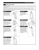
Page 27: ...nner Thigh Stretch Sit with the soles of your feet together with your knees pointing outward Pull your feet as close into your groin as possible Gently push your knees towards the floor Hold for 15 counts Hamstring Stretch Sit with your right leg extended Rest the sole of your left foot against your right inner thigh Stretch toward your toe as far as possible Hold for 15 counts Relax and then repe...

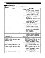
Page 28: ...irements section in this manual Program time has expired Treadmill will not incline Power fold models only Check for proper positioning of spring knob for folding See procedure in owners manual Treadmill will not unfold Power Fold only Check for proper positioning of spring knob for folding See procedure in owners manual Manual Fold only Folding locking lever is depressed Treadmill running belt mo...

Page 29: ...http www yowzafitness com 29 WARRANTY ...

Page 30: ...rioration caused by product location exposure or environment or conditions caused by unsuitable finishes cleaners or lubricants are not covered Loss from natural disasters such as hurricanes floods tornados etc are not covered Damage or breakage caused by unauthorized service installation alteration modification assembly or disassembly negligence or conditions of use which are unintended for the p...

Page 31: ...EQUENTIAL OR INCIDENTAL DAMAGES LOSSES OR EXPENSES INCLUDING BUT NOT LIMITED TO COMMERCIAL LOSSES BUSINESS INTERRUPTION OR DAMAGE TO PROPERTY OTHER THAN THE PRODUCT OR PRODUCTS TO WHICH THIS LIMITED WARRANTY APPLIES EFFECT OF STATE LAWS Some States do not allow limitations on how long an implied warranty lasts so the above limitation may not apply to you Some States do not allow the exclusion or l...

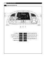
Page 32: ...ILL COMPUTER OPERATION A B C D E F I H G LCD DISPLAY A B INCLINE UP DOWN BUTTON STOP ENTER BUTTON C D EXPRESS INCLINE BUTTONS SAFETY KEY INSERT E F EXPRESS SPEED BUTTONS START BUTTON G H SPEED UP DOWN BUTTON MODE BUTTON I ...

Page 33: ...ine level per second and release the button to stop the function EXPRESS SPEED BUTTON Press the quick speed button to select the target speed EXPRESS INCLINE BUTTON Press the quick incline button to select the target incline MODE BUTTON Please MODE button the exchange the display IMPORTANT The console display will turn itself off automatically about five minutes after the bell has stopped moving T...

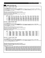
Page 34: ... UP DOWN button to run preset time target value and press START key DISTANCE Accumulates and displays workout distance from start of exercise CALORIES Accumulates and displays calories consume during workout time SPEED Displays current speed PROGRAM 2 DISTANCE 1 Press STOP ENTER to confirm the program 2 Press STOP ENTER before starting exercise to run presetting procedure with P2 blinking DISTANCE...

Page 35: ...8 8 5 5 6 4 4 0 4 8 3 0 1 6 1 0 2 KM ML 0 8 0 5 4 0 2 5 7 2 4 5 8 8 5 5 9 6 6 0 7 2 4 5 5 6 3 5 1 6 1 0 3 KM ML 0 8 0 5 4 8 3 0 8 0 5 0 9 6 6 0 10 4 6 5 8 0 5 0 6 4 4 0 1 6 1 0 4 KM ML 0 8 0 5 5 6 3 5 8 8 5 5 10 4 6 5 11 2 7 0 8 8 5 5 7 2 4 5 1 6 1 0 5 KM ML 0 8 0 5 6 4 4 0 9 6 6 0 11 2 7 0 12 0 7 5 9 6 6 0 8 0 5 0 1 6 1 0 6 KM ML 0 8 0 5 7 2 4 5 10 4 6 5 12 0 7 5 12 8 8 0 10 4 6 5 8 8 5 5 1 6 1 0...

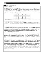
Page 36: ...your doctor s instruction then press the STOP ENTER buttons to save the setting Press the START button to start the three minute WARM UP program Speed starts from 2 0 mph 3 2 km h and the INCLINE LEVEL starts from level 0 Keep your hand on the hand pulse grips all the time during this workout in order to monitor your pulse correctly During the program if the heart rate monitor fails to sense the u...

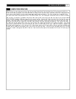
Page 37: ...e and Calories continue to count up from the warm up program During the HEART RATE CONTROL program the heart rate monitor will sense the actual user s pulse every 30 seconds If the actual user s pulse does not reach 85 of the max heart rate then the incline level will be increased by 1 level every 30 seconds If the actual user s pulse reaches 85 of the max heart rate then the treadmill performance...

Page 38: ...38 YOWZA JUNO TREADMILL ...

Page 39: ...http www yowzafitness com 39 ...

Page 40: ...40 YOWZA JUNO TREADMILL ...

Page 41: ......

Reviews: