background image

YO Power

User guide

v4.0

page 5/28

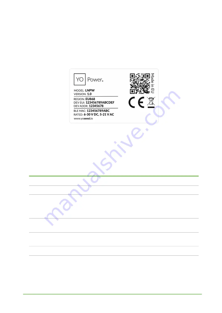
Device sticker placed on the right side of the device enclosure contains information about model,
version, LoRaWAN region and 3 parameters important in case of device identification and
configuration:

-

DEV EUI:

64-bit unique device identifier in a LoRaWAN network,

-

DEV ADDR:

address required to connect via ABP activation type to LoRaWAN,

-

BLE MAC:

bluetooth physical address.

Figure 2

Device sticker.

Physical interfaces

LEDs

YO Power communicates its current behavior to the user by RGBW LED placed on the top of the
device shown on figure one.

DIODE STATUES INTERPRETATION

BEHAVIOUR

COLOUR

DEVICE STATUS

Single flash

Green

General:

device is working correctly (power and memory).

Single flash

Red

General:

device is working incorrectly (power and memory).

LoRaWAN communication:

failed to receive an

acknowledgement from LoRaWAN Server within specified

timeout.

Single flash

White

LoRaWAN communication:

LoRaWAN frame sent \

confirmation from LoRaWAN Server after receiving the frame.

Slow flashing

Blue

BLE communication:

connection to the device via BLE

(configuration).

Rapid flashing

Blue

LoRaWAN communication:

connecting to LoRaWAN network.

Buttons

YO Power is equipped with one reset button inside the device on the PCB board under the
inscription “reset” shown on the figure 1. It is possible to press it with a thin stick.

www.yo

sensi

.

io

Summary of Contents for YO Power

Page 1: ...YO Power User guide v4 0...

Page 2: ...ns of the device Installation instruction upgraded device configuration and operation of the device updated payloads description added compliance statement 31 07 2023 4 0 Added CT clamps up to 1000 A...

Page 3: ...Package contents 9 Safety precautions 9 Installation guide 10 Operation 15 IoT system components 15 Device configuration 16 Configurable parameters 16 Parameters description 18 Configuration node with...

Page 4: ...ingle phase devices etc It is possible to install current clamps without knowing the direction through which the current flows Wireless communication eliminates the need for additional wiring or conve...

Page 5: ...STATUES INTERPRETATION BEHAVIOUR COLOUR DEVICE STATUS Single flash Green General device is working correctly power and memory Single flash Red General device is working incorrectly power and memory L...

Page 6: ...vice PHYSICAL SPECIFICATION Dimensions Height 90 mm Width 71 2 4 pole mm Depth 58 mm Colour Light grey Mounting method 35 mm DIN rail Vertical can be screwed to the wall Enclosure material Polycarbona...

Page 7: ...T Model 50mA 200 A 3 CT Model 50mA 400 A 3 CT Model 50mA 600 A 3 CT Model 50mA 800 A 3 CT Model 50mA 1000 A 3 Power consumption 0 230 V Not given in datasheet Current YO Power offers automatically swi...

Page 8: ...easured by YO Power and attached to it CT clamps is a value calculated for each hour for 230 V and current flowing on each channel It helps monitor customers how much power is consumed by the devices...

Page 9: ...cing battery connecting input or doing some other operations near inside electronics Be careful while handling the device dropping it may cause damage that will affect the sensors and other electronic...

Page 10: ...YO Power User guide v4 0 page 10 28 Installation guide 1 Mount the device on a 35 mm DIN rail Figure 6 Device mounting instructions www yosensi io...

Page 11: ...e v4 0 page 11 28 2 Connect the inputs to the individual channels of the device according to the polarity shown on the enclosure label Figure 7 Connect the inputs to the individual channels of the dev...

Page 12: ...page 12 28 3 Fasten the current clamps around the wires in which the current is to be measured a clamp should be placed around one wire Figure 8 Instruction on how to fasten the current clamps around...

Page 13: ...O Power User guide v4 0 page 13 28 4 Screw the power supply wires to the device regardless of polarity 6 30 V DC 5 21 V AC Figure 9 Instruction on how to connect the power to the device www yosensi io...

Page 14: ...YO Power User guide v4 0 page 14 28 Figure 10 Final look of the device www yosensi io...

Page 15: ...ay 2 Gateway device similar to routers equipped with a LoRa concentrator that receives LoRa packets and send them to the Internet connected server 3 Server in most cases a cloud based service where da...

Page 16: ...vidual configuration for a specific device this section s structure differs for each device Sample configuration file for the YO Power device info devmodel LNPW fwver 3 5 0 loraradio SX1261 lorawanver...

Page 17: ...EUI Extended Unique Identifier 8 B HEX predefined R W appeui Application EUI 8 B HEX predefined R W appkey Application Key 16 B HEX predefined R W trials Join request trials 1 9 3 R W lorawan abp deva...

Page 18: ...ific to the particular MCU and are unique for each device they can be changed if needed interval determines the interval of sending broadcast packets used to connect to every BLE receiver around the d...

Page 19: ...10 3 911 7 MHz channels 40 47 6 Sub band 7 911 9 913 3 MHz channels 48 55 7 Sub band 8 915 5 914 9 MHz channels 56 63 8 AU915 Sub band 1 915 2 916 6 MHz channels 0 7 1 2 R W Sub band 2 916 8 918 2 MHz...

Page 20: ...ent buttons Configure here you can change and upload the device parameters Update firmware here you can update the firmware to version 3 4 0 and newer Recover device this section restores the firmware...

Page 21: ...si io The application is a representation of each system and together with the node definitions is created by customers The basic integration of a node into the Yosensi Management Platform is describe...

Page 22: ...section appkey All device identifiers are provided by Yosensi Support when you order the nodes Select a model that is compatible with your device this choice affects the number of charts and data sour...

Page 23: ...de configuration Click on the link in the Node Name column Go to the KEYS tab and switch LoRa Type from OTAA to ABP and fill in the blank spaces then press update The identifiers Device Address devadd...

Page 24: ...plication click the bottom right button Fill in the Name and Description fields and select the Application Profile which is the region definition 4 Proceed to the application by clicking its name on t...

Page 25: ...4a 2e 2a 11 01 02 ad 2e 2a Second frame 02 03 01 16 2e 00 11 03 02 a5 2e 00 11 04 02 70 2e 01 11 05 02 a9 2e 01 11 06 02 a1 2e 09 11 01 00 01 2e 09 11 02 00 00 2e 09 The payload starts building from t...

Page 26: ...s 0 addr_len 1 meas_len 2 addr 5 val 781 7 81 A Fifth measurement CH6 current 0x2E 0x00 0x11 0x06 0x03 0x4A type 11 prec 2 md s 0 addr_len 1 meas_len 2 addr 6 val 845 8 45 A Sixth measurement CH1 curr...

Page 27: ...YO Power User guide v4 0 page 27 28 Compliance statements www yosensi io...

Page 28: ...YO Power User guide v4 0 page 28 28 www yosensi io...

Reviews: