


To get the full Owner’s Manual please visit our website at
http://www.yorkville.com/manuals/
or, if you need a printed version call
905-837-8777
Printed In CANADA
QuickStart-YCV4050-00-1v1 • YS#QSTART-YCV4050 • January 22, 2020
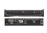
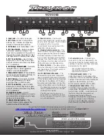
1. Input jack –
1/4 inch phone jack
2. Ch 1 Gain –
Works in conjunction
with the Ch 1 Volume to adjust the
amount of tube-based overdrive.
3. Ch 1 Volume –
sets the loudness of Ch 1.
4. Ch 1 Boost Switch –
helps to achieve
‘a-bit-more’ overdrive for leads. The
boost can be selected via the switch or
through the supplied footswitch. A Red
LED illuminates to indicate when active.
5. Ch 1 Tone Controls –
used to help
shape your sound. They’re post-gain
and pre-volume and active only when
Ch 1 is selected.
6. Ch 1 Vintage / Modern Switch –
A smooth,
”vintage” voice or a more aggressive
“modern” voice can be selected.
7. Channel Select Switch –
When selected,
Ch 2 is active and the green LED next to
the Ch 2 Volume is illuminated.
8. Ch 2 Volume –
Ch 2’s gain is preset
and is set optimumly for a clean
sound and has no Gain control.
9. Ch 2 Tone Controls –
used to help
shape your sound. They’re post-gain
and pre-volume and active only when
Ch 2 is selected.
10. Brightness Switch –
Ch 2’s
Brightness switch activates a circuit to
provide additional treble boost to help
make your tone sparkle.
11. Master Volume Control –
The
Master Volume control adjusts the
overall volume of the amplifier.
12. Reverb Control –
The Reverb
control that adjusts the overall reverb
level for both channels. The YCV4050
is equipped with a long-style
Accutronics® dual-spring reverb for
authentic vintage reverb.
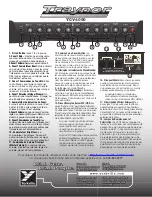
13. Standby Switch & Indicator –
This
switch controls the high voltage power
being supplied to the tubes and keeps
the tubes warmed up when the amp
is not in use. The large, jewel indicator
changes from Red to Yellow when the
high voltage circuit has been turned off.
Putting the amp into Standby mode.
14. Power Indicator –
The jewel glows
Red when the amp is fully powered-up
and operational. The Power switch is
located on the rear panel.
15. EFX / LINE Send & Rtn Jacks –
The
Send and Rtn jacks allow convenient
use of an external effect unit. Connect a
1/4 inch phone cable from the Send jack
to the Input of the effects unit. To send
the processed signal back, connect the
output of the effects unit to the Rtn jack.
The Send jack can be used as a direct
line out (preamp-out) ot to slave with
another guitar amplifier.
The Rtn jack can be used as a
power amp in. The Master Control
section regulates the signal so you
can still add Reverb.
16. Footswitch Jack –
Connecting a
footswitch to this jack deactivates the
front panel Channel Select and Boost
switches. Functions are then activated
exclusively by the pedal.
The included footswitch features
dual-latching switches, each with a
separate LED indicator.
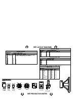
17. External Speaker Jack/s –
The
under-the-chassis 1/4 inch jacks allow
connection of an 8-ohm external speaker
cabinet. If the internal 12-inch Celestion®
speaker is disconnected, up to two
8-ohm external cabinets can be used.
18. Replacement Tubes & Bias –
The
YCV4050 comes equipped with 6L6
output tubes. Replacements can be any
brand of 6L6 or 5881 - we recommend
the bias voltage be measured and
adjusted (see Owner’s Manual).
Swapping in EL34/6CA7 output tubes
require a change in one of the bias
resistors. The modification should be
performed by a qualified technician.
YCV4050
Gain
0
5
10
0
5
10
0
5
10
0
5
10
0
5
10
0
5
10
0
5
10
0
5
10
0
5
10
0
5
10
0
5
10
CHANNEL
CHANNEL
SELECT
SELECT
Vintage /
Modern
1
2
Volume
Middle
Bass
Treble
Volume
Middle
Bass
Treble
Reverb
Power
STANDBY
STANDBY
BRIGHTNESS
BOOST
Input
Master
Volume
Send
EFX / Line
Footswitch
Rtn
Ch. Select
/ Boost
Extension
Speaker
POWER
6L6B
V4
6L6B
V5
PREAMP
SPLITTER
12AX7
V3
12AX7
V2
12AX7
V1
DÉBRANCHÉ L’APPAREIL AVANT
DE REMPLACER LES LAMPES
DISCONNECT POWER WHEN
REPLACING TUBES
THIS UNIT MUST BE GROUNDED!
CET APPAREIL DOIT ÊTRE MIS À LA TERRE!
10
13
7
8
15
16
17
14
11
12
9
1
2
4
3
5
6


