YORKVILLE COLISEUM CA1 Owner'S Manual Download Page 11

11

INSTALLATION NOTES 

At all times, the amplifier has to be operated under appropriate conditions. This 

includes that the operation location provided sufficient ventilation and the device is 

not exposed to direct sunlight or direct radiation or reflection from any heat source. 

Installing the loudspeaker systems choose a location that gets not affected by ex

-

treme and/or constant vibration or other mechanical oscillation. Also make sure that 

the speakers are installed at locations that are free from dust and/or moisture. 

 CAUTION 

We strongly recommend that you leave the connection of the appliance to the qualified 

and experienced service technical who is specialized in connecting electrical and electroni

-

cally equipment. Do not take the risk of electro-shock or shock hazard. To reduce the risk of 

electro-shock all connections have to be accomplished before it is permissible to connect 

the amplifier to the main supply. Before connecting the appliance to the mains supply, once 

again make certain that all connections are carried out correctly and that no short-circuits 

exist. The overall sound reinforcement installation has to be in accordance to the laws regu

-

lations, standards and guidelines that are relevant and applicable in the country where the 

equipment is going to be operated. 

AC POWER SUPPLY 

 CAUTION 

Before using the amplifier for the first time make sure that the appliance IS set in ac

-

cordance to your mains supply. Otherwise, please consult your Yorkville dealer who 

will configure your equipment for the correct voltage. Connect the amplifier only to 

grounded mains outlets. Connecting the amplifier to the mains supply (115Vac re

-

spectively 230Vac) has to be accomplished by inserting the supplied mains cord into 

the corresponding socket (15) and afterward plugging it into a mains outlet.

DC POWER SUPPLY 

 CAUTION 

A 24V DC power source (i e. a battery) has to be connected to the terminals (18) that 

are covered by the protective lid. To reduce the risk of dropping voltage to a minimum 

and to eliminate the danger of damaging the battery cables by thermal overload, 

these cables have to be at least 2.5mm

2

 in diameter, each. Switching the amplifier on 

or off is performed through the power switch (33). 

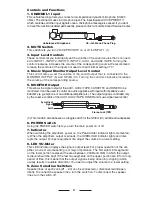
CONNECTING THE OUTPUT TERMINALS

 CAUTION  

To avoid the risk of electrical shock, 

never touch

 the bare conductors leading to the 

output terminals of the amplifier when it is in operation. Under figures, show the pos

-

sible connections of thee OUTPUT speaker terminals accessible by removing the 

protective cover. Bear in mind the following rules: 

Constant Impedance Lines

• The total impedance of the speakers connected 

must correspond to that selected 

on amplifier’s output terminals. 

• The sum of the power capacities of the speakers must be no lower than the amplifier’s 

power capacity.
• The length of the connecting cables must be as possible; in any case, the longer the 

distance to be covered and the greater must be the cross-section of the cables. 

Constant voltage lines 

• Each speaker must be equipped with a line transformer with an input voltage equal 

to that of the line (25, 70, 100V). 
• The sum of the power capacities of the speakers must 

not exceed the output 

power capacity of the amplifier (i.e. total wattage of speakers installed in zones 

1 through 4). 

Summary of Contents for COLISEUM CA1

Page 1: ...TREBLE MASTER ZONE 1 ZONE 2 ZONE 3 ZONE 4 ALL MUTE INPUT POWER Peak Limiter ON OFF OUTPUT LEVEL C O L I S E U M 10 9 8 2 1 7 3 0 6 5 4 10 9 8 2 1 7 3 0 6 5 4 10 9 8 2 1 7 3 0 6 5 4 10 9 8 2 1 7 3 0 6...

Page 2: ...nt les instructions contenues dans ce manuel Veuillez conserver pour r f rences futures Ce manuel est important pour l op ration de ce produit et doit l accompagner lorsque le produit change de propri...

Page 3: ...ional zone paging functions four zone paging and all zone paging Optional DTS AM FM tuner Only CA1T CA1T PROFESSIONAL PUBLIC ADDRESS POWER AMPLIFIER CHANNEL 1 CHANNEL 2 CHANNEL 3 CHANNEL 4 CHANNEL 5 C...

Page 4: ...0ohms e g earphone or an additional amplifier etc The output signal is controlled only by the volume controls of the AUX1 AUX2 TAPE TUNER and music signal level control 4 This function also behaves as...

Page 5: ...n be operated if this knob is rotated clockwise and an indication appears on the display ii Rotate the volume control clockwise to increase the radio s output signal level ii Display This display indi...

Page 6: ...CD PLAYER 4 AUX IN CHANNEL 6 INPUT L R L R CHANNEL 5 INPUT CHANNEL 4 INPUT CHANNEL 3 INPUT CHANNEL 2 INPUT MIC LINE 24V MIC LINE 24V MIC LINE 24V AUX 2 AUX 1 2 AM FM RADIO 3 CASSETTE PLAYER 1 4 2 3 CO...

Page 7: ...be used default is constant voltage 70V output 19 Output Terminal Strip These 5 terminals allow connecting speakers COM 25V 70V 100V DC 24V 15A 4 24Vdc COM 0 70V COM COM Zone 4 Zone 3 Zone 2 Zone 1 0...

Page 8: ...output stage of the power ampli fier This opportunity provides a proper solution whenever shaping or improving the audio signal is necessary adjusting delay times equalizing eliminating the Larsen eff...

Page 9: ...NPUT 3 and INPUT 4 lnputs Sensitivity and XLR Phantom Power 24V Switch By turning these switchs to the LINE position INPUT 2 INPUT 3 and INPUT4 can be connected to an audio source with high level sign...

Page 10: ...these terminals i e by means of using an electrical switch the audio signals coming from AUX1 AUX2 TAPE CASSETTE and TUNER are attenu ated while the signals coming from INPUT1 INPUT2 and INPUT4 have...

Page 11: ...rrect voltage Connect the amplifier only to grounded mains outlets Connecting the amplifier to the mains supply 115Vac re spectively 230Vac has to be accomplished by inserting the supplied mains cord...

Page 12: ...0dB 1V 1OK unbalanced Outputs for speakers ohms 4 ohms Outputs for speakers Volts 25V 70V 100V 10 83 170 25V 70V 100V 5 42 83 Additional outputs PRE OUT mono RCA jack 1V 600 unbalanced voltage impeda...

Page 13: ...5 4 10 9 8 2 1 7 3 0 6 5 4 10 9 8 2 1 7 3 0 6 5 4 PLL AM FM RADIO M1 M2 M3 M4 M5 MEMORY DOWN UP AM FM VOL Microphone Microphone Stand Headphones CA1 PROFESSIONAL PUBLIC ADDRESS POWER AMPLIFIER CHANNE...

Page 14: ...GND C O L I S E U M PROFESSIONAL PUBLIC ADDRESS POWER AMPLIFIER FUSE T 5 0 A CAUTION REPLACE WITH SAME TYPE FUSE AND RATING ATTENTION UTILISER UN FUSIBLE DE RECHANGE DE MEME TYPE ET CALIBRE DESIGNED...

Page 15: ...es Alimentation de courant direct 24 Vdc Fonction de dispositif de recherche zone optimale dispositif de recherche pour quatre zones et pour toutes les zones Syntoniseur AM FM DTS optionnel CA1T seule...

Page 16: ...d aux entr es AUX1 AUX2 TAPE CAS SETTE et TUNER Il peut tre employ pour commander un appareil audio avec une im p dance d entr e au dessus de 600ohms ex couteurs ou amplificateur additionnel Le signal...

Page 17: ...l e la position centrale 13 Syntoniseur AM FM DTS Optionnel CAIT seulement i Radio ON OFF et commande de volume VOL La radio peut tre utilis e si cette commande est tourn e dans le sens horaire et une...

Page 18: ...M PROFESSIONAL PUBLIC ADDRESS POWER AMPLIFIER FUSE T 5 0 A CAUTION REPLACE WITH SAME TYPE FUSE AND RATING ATTENTION UTILISER UN FUSIBLE DE RECHANGE DE MEME TYPE ET CALIBRE DESIGNED MANUFACTURED FOR Y...

Page 19: ...e Il est donc recommand d avoir un dispositif appropri port de la main Quand l amplificateur est op r avec un source d alimentation CC la capacit de puissance nominale est r duite d approximativement...

Page 20: ...e Le signal asym trique est affect par les com mandes d entr e individuelle Avant d utiliser la sortie PRE OUT vous devez enlever la bande de pont entre cette borne et la borne MAIN IN 21 COM 25V 70V...

Page 21: ...hones dynamique 30 600 ohms ou le raccordement d une source sonore avec niveau lev ex syntoniseur AM FM magn tophone cassette lecteur CD etc Dans le cas o vous l utilisez il est n cessaire d utiliser...

Page 22: ...est la position 3 les entr es AUX1 et AUX2 peuvent accepter les signaux de sortie provenant de magn tophone cassette Lors que ce s lecteur est la position 4 les entr es AUX1 et AUX2 peuvent accepter l...

Page 23: ...mandons fortement de laisser le raccordement de l appareil un technicien de service qualifi et exp riment qui se sp cialise dans le raccordement d appareil lectrique et lectronique vitez de prendre de...

Page 24: ...de haut parleur accessible en enlevant le couvercle pro tecteur Consid rez les r gles suivantes Imp dance de ligne constante L imp dance total des haut parleurs connect s doit corresponde celle s lec...

Page 25: ...pour haut parleurs ohms 4 ohms Sorties pour haut parleurs Volts 25V 70V 100V 10 83 170 25V 70V 100V 5 42 83 Sorties Additionnels PRE OUT mono RCA jack 1V 600 asym trique voltage imp dance Haut parleur...

Page 26: ...5 4 10 9 8 2 1 7 3 0 6 5 4 10 9 8 2 1 7 3 0 6 5 4 PLL AM FM RADIO M1 M2 M3 M4 M5 MEMORY DOWN UP AM FM VOL Microphone Microphone Stand Headphones CA1 PROFESSIONAL PUBLIC ADDRESS POWER AMPLIFIER CHANNE...

Page 27: ...GND C O L I S E U M PROFESSIONAL PUBLIC ADDRESS POWER AMPLIFIER FUSE T 5 0 A CAUTION REPLACE WITH SAME TYPE FUSE AND RATING ATTENTION UTILISER UN FUSIBLE DE RECHANGE DE MEME TYPE ET CALIBRE DESIGNED...

Page 28: ...Niagara Falls New York 14305 USA Voice 716 297 2920 Fax 716 297 3689 WORLD HEADQUARTERS CANADA Yorkville Sound 550 Granite Court Pickering Ontario L1W 3Y8 CANADA Voice 905 837 8481 Fax 905 837 8746 Pr...

Reviews: