


1
AUDIOPRO AP-3400 SERVICE MANUAL
M1012A “THE INPUT BOARD”
The input board processes the audio signal from the input jacks to the voltage amplifier board, (M1011A).
Each channel consists of a balanced gain stage, defeatable bass boost filter, and a preemphasis filter network.
The balanced input, (XLR Jack) and unbalanced input (phone jack) are wired in parallel to the input of a balanced
operational amplifier, (U1). The gain of this stage is 1.6 (4dB) balanced and 1.6 (4dB) unbalanced. Resistors R1, R5
along with capacitors C1 and C2 form a radio interference elimination filter.
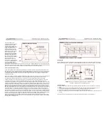
Switch S1 selects a flat or bass boosted frequency response. The bass boost filter provides a 20Hz high pass, high Q
filter response with a +4dB peak at 55Hz. The filter consists of a tee network on the input of U1A along with R9, R10,
R11, C5 and C6. The gain is 1 (0dB) in the passband, (above 100Hz).
Operational amplifier U3B is a high pass shelving filter with a +2dB shelf above 20KHz. This filter provides the pre-
emphasis required to obtain a flat frequency response (to 20KHz) on the power amplifier output at full power.
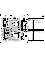
M1011A "VOLTAGE AMPLIFIERS AND SYSTEM CONTROL"
This board contains:
•
Voltage amplifiers to drive the current amplifiers on the M1002A boards.
•
The front panel volume control circuitry.
•
The EMS control system with its associated circuits: Pre clipping and line current sensing heater circuits.
•
Clip and activity LED's. Driver circuitry for the amplifier disable relay (used during amplifier turn on, turn off,
thermal shutdown and current limiting).
Circuit Explanation:
Refer to the schematic of M1011A as the sections of the circuit are explained.
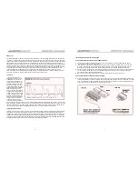
The audio signal enters the board from M1012A through connector MS4. The two channels are marked "L" and "R"
for left and right. The signals are to be considered as differential sources and therefore are marked as L+, L-,R+ and
R-. Since the left channel has the same topology as the right channel we will only look at the left channel.
The signal ("L+") at the terminal block (MS4) passes through the front panel level control (P1) and the desired level
enters the inverting input of U1.
Op amp U1 is an inverting amplifier with a set gain of 2.40 (7.6dB). Built around U1 is a dual purpose circuit controlled
by a voltage divider consisting of R15, R16, R17, R18, R19, R20 and R21. The voltage divider sets two reference
levels, (HDRM & CLP). Reference voltage levels vary with the voltage levels on the +/-144VDC supply rails. As the
amplifier?s output is loaded, the supply rails voltage decreases and so do the reference levels.
Transistors Q1, Q3 the surrounding resistors provide a pre-clipping function that tracks the supply rails through the
HDRM voltage reference and clips the audio signal at approximately 11.2V pk. The clip LED indicator circuit is
connected through D1 and D2 to the output of U1, The bases of Q2 and Q4 are connected to the “CLP” reference
voltage, and when the peak output voltage of U1 (+/-Vp) is enough to forward bias the transistor junctions, Q2 or Q4
will trigger the clip led circuit (Q5), and illuminate the clip LED.
The audio signal on the output of U1 enters U3 through R43 and RV1. Under normal operating conditions the gain of
U3 is 1(0dB). The signal then passes through U2 to the voltage amplifier.
The exclamation point within an equilatereal
triangle is intended to alert the user to the
presence of important operating and
maintenance (servicing) instructions in the
literature accompanying the appliance.
Le point d’exclamation à l’intérieur d’un triangle équilatéral
est prévu pour alerter l’utilisateur de la présence
d’instructions importantes dans la littérature accompag-
nant l’appareil en ce qui concerne l’opération et la
maintenance de cet appareil.
This lightning flash with arrowhead symbol,
within an equilateral triangle, is intended to alert
the user to the presence of uninsulated
“dangerous voltage” within the product’s enclosure
that may be of sufficient magnitude to constitute a risk of
electric shock to persons.
Ce symbole d’éclair avec tête de flèche dans un triangle
équilatéral est prévu pour alerter l’utilisateur de la présence
d’un « voltage dangereux » non-isolé à proximité de l’enceinte
du produit qui pourrait être d’ampleur suffisante pour présenter
un risque de choque électrique.
IMPORTANT SAFETY INSTRUCTIONS
safety-4v5.eps • April 3/2007
CAUTION
:
TO REDUCE THE RISK OF ELECTRIC
SHOCK, DO NOT REMOVE COVER (OR BACK).
NO USER SERVICEABLE PARTS INSIDE.
REFER SERVICING TO QUALIFIED
SERVICE PERSONNEL.
FOLLOW ALL INSTRUCTIONS
SUIVEZ TOUTES LES INSTRUCTIONS
Instructions pertaining to a risk of fire,
electric shock, or injury to a person
Read Instructions:
The Owner’s Manual should be read and
understood before operation of your unit. Please, save these instruc-
tions for future reference and heed all warnings.
Clean only with dry cloth.
Packaging:
Keep the box and packaging materials, in case the unit
needs to be returned for service.
Warning:
To reduce the risk or fire or electric shock, do not expose
this apparatus to rain or moisture.
Do not use this apparatus near water!
Warning:
When using electric products, basic precautions should
always be followed, including the following:
Power Sources
Your unit should be connected to a power source only of the voltage specified in the
owners manual or as marked on the unit. This unit has a polarized plug. Do not use
with an extension cord or receptacle unless the plug can be fully inserted. Precau-
tions should be taken so that the grounding scheme on the unit is not defeated.
Hazards
Do not place this product on an unstable cart, stand, tripod, bracket or table. The
product may fall, causing serious personal injury and serious damage to the product.
Use only with cart, stand, tripod, bracket, or table recommended by the manufacturer
or sold with the product. Follow the manufacturer’s instructions when installing the
product and use mounting accessories recommended by the manufacturer.
The apparatus should not be exposed to dripping or splashing water; no objects
filled with liquids should be placed on the apparatus.
Terminals marked with the “lightning bolt” are hazardous live; the external wiring
connected to these terminals require installation by an instructed person or the use of
ready made leads or cords.
Ensure that proper ventilation is provided around the appliance. Do not install near
any heat sources such as radiators, heat registers, stoves, or other apparatus
(including amplifiers) that produce heat.
No naked flame sources, such as lighted candles, should be placed on the apparatus.
Power Cord
Do not defeat the safety purpose of the polarized or grounding-type plug. A polarized plug
has two blades with one wider than the other. A grounding type plug has two blades and a
third grounding prong. The wide blade or the third prong are provided for your safety. If the
provided plug does not fit into your outlet, consult an electrician for replacement of the
obsolete outlet. The AC supply cord should be routed so that it is unlikely that it will be
damaged. If the AC supply cord is damaged DO NOT OPERATE THE UNIT.
Unplug this apparatus during lightning storms or when unused for long periods of time.
Service
The unit should be serviced only by qualified service personnel.
AVIS:
AFIN DE REDUIRE LES RISQUE DE CHOC
ELECTRIQUE, N’ENLEVEZ PAS LE COUVERT (OU LE
PANNEAU ARRIERE)
NE CONTIENT AUCUNE PIECE
REPARABLE PAR L’UTILISATEUR.
CONSULTEZ UN TECHNICIEN QUALIFIE
POUR L’ENTRETIENT
Instructions relatives au risque de feu,
choc électrique, ou blessures aux personnes
Veuillez Lire le Manuel:
Il contient des informations qui devraient
êtres comprises avant l’opération de votre appareil. Conservez.
Gardez S.V.P. ces instructions pour consultations ultérieures et
observez tous les avertissements.
Nettoyez seulement avec le tissu sec.
Emballage:
Conservez la boite au cas ou l’appareil devait être
retourner pour réparation.
Avertissement: Pour réduire le risque de feu ou la décharge
électrique, n'exposez pas cet appareil à la pluie ou à l'humidité.
N’utilisez pas cet appareil près de l’eau!
Attention:
Lors de l’utilisation de produits électrique, assurez-vous
d’adhérer à des précautions de bases incluant celle qui suivent:
Alimentation
L’appareil ne doit être branché qu’à une source d’alimentation correspondant au
voltage spécifié dans le manuel ou tel qu’indiqué sur l’appareil. Cet appareil est
équipé d’une prise d’alimentation polarisée. Ne pas utiliser cet appareil avec un
cordon de raccordement à moins qu’il soit possible d’insérer complètement les trois
lames. Des précautions doivent êtres prises afin d’eviter que le système de mise à la
terre de l’appareil ne soit désengagé.
Risque
Ne pas placer cet appareil sur un chariot, un support, un trépied ou une table instables.
L’appareil pourrait tomber et blesser quelqu’un ou subir des dommages importants.
Utiliser seulement un chariot, un support, un trépied ou une table recommandés par le
fabricant ou vendus avec le produit. Suivre les instructions du fabricant pour installer
l’appareil et utiliser les accessoires recommandés par le fabricant.
Il convient de ne pas placer sur l’appareil de sources de flammes nues, telles que
des bougies allumées.
L’appeil ne doit pas être exposé à des égouttements d’eau ou des éclaboussures
et qu’aucun objet rempli de liquide tel que des vases ne doit être placé sur l’appareil.
Assurez que lappareil est fourni de la propre ventilation. Ne procédez pas à
l’installation près de source de chaleur tels que radiateurs, registre de chaleur, fours
ou autres appareils (incluant les amplificateurs) qui produisent de la chaleur.
Les dispositifs marqués d’une symbole “d’éclair” sont des parties dangereuses
au toucher et que les câblages extérieurs connectés à ces dispositifs de
connection extérieure doivent être effectivés par un opérateur formé ou en utilisant
des cordons déjà préparés.
Cordon d’Alimentation
Ne pas enlever le dispositif de sécurité sur la prise polarisée ou la prise avec tige de
mise à la masse du cordon d’alimentation. Une prise polarisée dispose de deux
lames dont une plus large que l’autre. Une prise avec tige de mise à la masse
dispose de deux lames en plus d’une troisième tige qui connecte à la masse. La
lame plus large ou la tige de mise à la masse est prévu pour votre sécurité. La prise
murale est désuète si elle n’est pas conçue pour accepter ce type de prise avec
dispositif de sécurité. Dans ce cas, contactez un électricien pour faire remplacer la
prise murale. Évitez d’endommager le cordon d’alimentation. N’UTILISEZ PAS
L’APPAREIL si le cordon d’alimentation est endommagé.
Débranchez cet appareil durant les orages ou si inutilisé pendant de longues périodes.
Service
Consultez un technicien qualifié pour l’entretien de votre appareil.
S2125A


