


JOHNSON CONTROLS
19
Section 2 - Installation
Form 160.78-N1
Issue date: 2/02/2022
2
Make connections
After the unit is leveled, place wedges and/or shims un-
der each corner to solidly support the unit in this position
while connecting and hanging the piping, adjusting the
connections, and checking for proper alignment.
After the connections are made and insulation is applied,
the unit can be filled with water and checked for leaks.
If spring isolators were installed, final adjustments
can be made to the leveling bolts until the wedges and
shims can be removed. The unit should now be in cor-
rect level position, clear of the floor or foundation and
without any effect from the weight of the piping.
The coolant temperature inside any liquid-cooled motor
starter supplied by Johnson Controls must be maintained
above the dewpoint temperature in the equipment room
to prevent condensing water vapor inside the starter
cabinet. Therefore, an additional temperature-controlled
throttle valve is needed in the flow path for the starter
heat exchanger to regulate cooling above the equipment
room dewpoint for applications using cooling sources
other than evaporative air-exchange methods, such as
wells, bodies of water, and chilled water. The tempera-
ture control valve should be the type to open on increas-
ing drive coolant temperature, fail-closed, and set for
a temperature above dewpoint. It can be requested as
factory-supplied on a chiller order by special quotation.
Piping connections
After the unit is leveled (and wedged in place for op-
tional spring isolators) the piping connections may be
made; chilled water, condenser water and refrigerant
relief. The piping should be arranged with offsets for
flexibility, and adequately supported and braced inde-
pendently of the unit to avoid strain on the unit and
vibration transmission (see
low for alignment of pipe. Isolators supplied by others
in the piping and hangers are preferred. The isolators
may be required by specifications to effectively use the
vibration isolation characteristics of the vibration iso-
lation mounts of the unit.
Check for piping alignment: On completion of pip-
ing, open a connection in each line as close to the unit
as possible by removing the flange bolts or coupling
and check for piping alignment. If any of the bolts are
bound in their holes, or if the connection springs are
out of alignment, the misalignment must be corrected
by properly supporting the piping or by applying heat
to anneal the pipe.
If the piping is annealed to relieve stress,
the inside of the pipe must be cleaned of
scale before it is finally bolted in place.
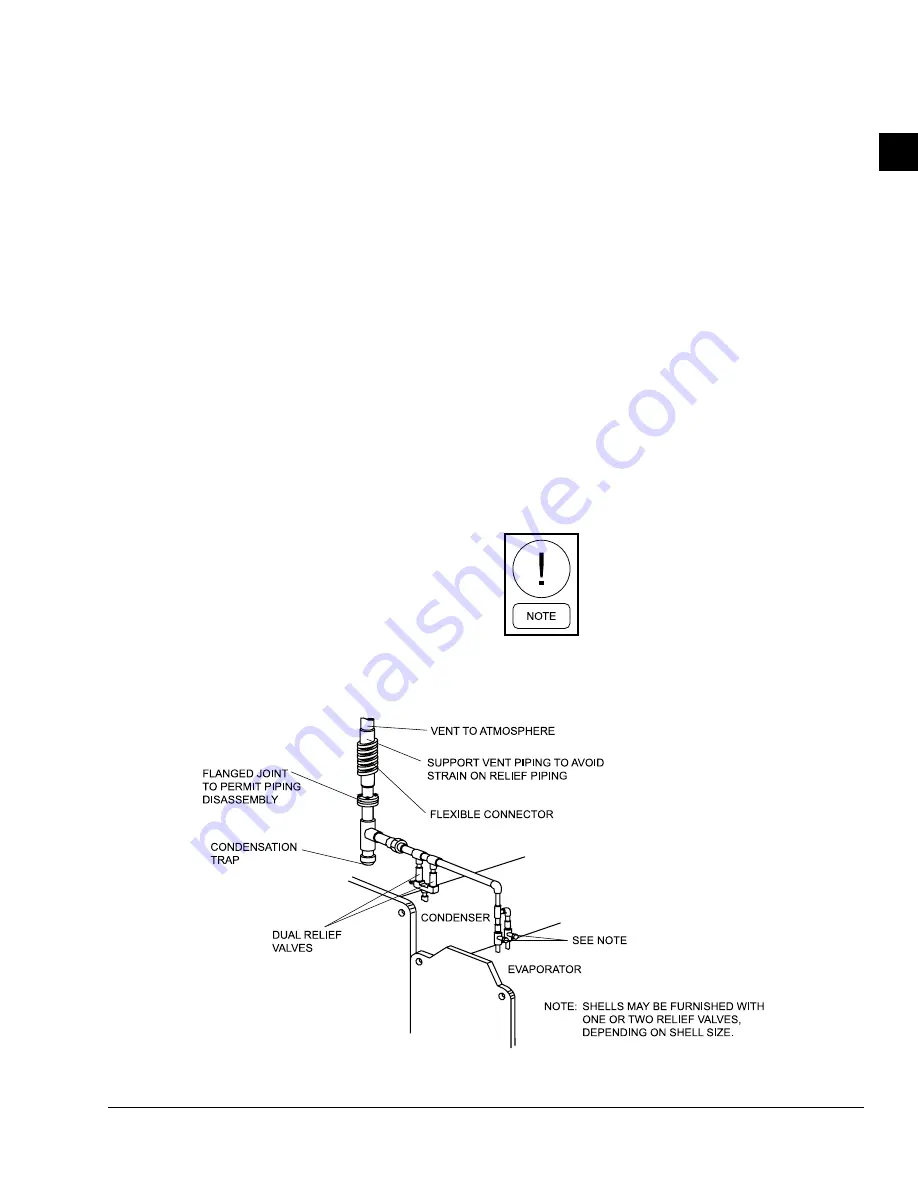
Figure 7 -
Typical refrigerant vent piping
LD03863