


JOHNSON CONTROLS
19
FORM 160.69-NM4
ISSUE DATE: 9/30/2020
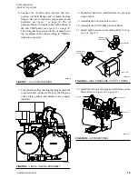
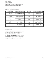
6. Connect the oil drain lines between the com-
pressors oil drain flanges and oil pump housing
flanges. Be sure to install the proper gaskets and
hardware, see
. The oil
pump and heater wiring have been disconneted at
the unit VSOP panel, see
The wiring has been secured to the oil pump hous-
ing for shipment. Reconnect wiring to VSOP lo-
cated on evaporator.
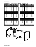
FIGURE 7 -
OIL PUMP HOUSING
LD09442
7. Complete the refrigerant liquid piping beneath the
evaporator and condenser. Be sure the fill piece,
orifice plate, gaskets and hardware are properly
installed.
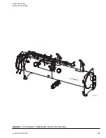
FIGURE 8 -
LIQUID LINE RE-ASSEMBLY
LD09435a
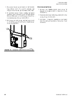
8. Tighten all hardware installed from the previous
steps 2 thru 8.
9. Assemble the Control Center to unit.
10. Assemble the VS Oil Pump Control Panel.
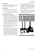
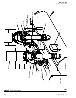
11. Install high pressure cutout tubing. Refer to
FIGURE 9 -
HIGH PRESSURE CUTOUT TUBING
LD09431
Isolation Valve
with Actuator
Compressor #1
VSOP Panel
Isolation Valve
with Actuator
Compressor #2
12. Install the refrigerant piping and oil return system
filters. Refer to
FIGURE 10 -
SYSTEM PIPING
LD09433
Compressor #2
Compressor #1
VSOP Panel


