


YORK INTERNATIONAL
17
FORM 201.19-W3 (1104)
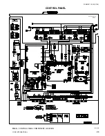
CAUTION:
No Controls (relays, etc.) should
be mount ed in the Smart Panel
en clo sure or con nect ed to pow er
sup plies in the control pan el.
Additionally, con trol wir ing not
con nect ed to the Smart Panel
should not be run through the
cabinet. This could re sult in
nui sance faults.
CAUTION:
Any inductive devices (re lays)
wired in series with the flow
switch for start/stop, into the
Alarm cir cuit ry, or pilot relays
for pump start ers wired through
mo tor contactor aux il ia ry con-
tacts must be sup pressed with
YORK P/N 031-00808-000
sup pres sor across the re lay/
contactor coil.
Any contacts con nect ed to fl ow
switch inputs or BAS in puts on
ter mi nals 13 - 19 or TB3, or any
oth er ter mi nals, must be sup-
pressed with a YORK P/N 031-
00808-000 sup pres sor across the
re lay/con tac tor coil.
CAUTION:
Control wiring con nect ed to the
con trol panel should nev er be run
in the same con duit with pow er
wir ing.
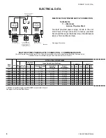
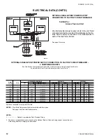
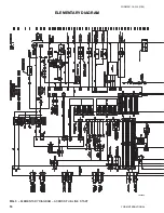
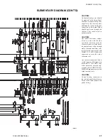
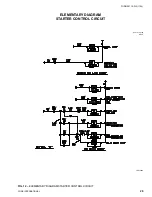
ELEMENTARY DIAGRAM (CONT'D)
UNIT
CONTROL
MIN
MAX DUAL
NON-FUSED
VOL
TAGE
POWER
CIRCUIT
ELEMENT
DISC.
SUPPL
Y
AMP
.
FUSE SIZE
SWITCH SIZE
ALL
MODELS
11
5-1-50/60
20A
20A
250V
30A
240V
W/O
TRANS.
MODELS
-17
200-1-60
15A
15A
250V
30A
240V
WITH
-28
230-1-60
15A
15A
250V
30A
240V
TRANS.
-46
400-1-60
8A
8A
600V
30A
480V
*
-58
575-1-60
8A
8A
600V
30A
600V
*
All primary and secondary wiring between transformer and control panel in
clud
ed.
CONTROL POWER SUPPL
Y
LD09481
Summary of Contents for YCAS Series
Page 5: ...YORK INTERNATIONAL 5 FORM 201 19 W3 1104 This page intentionally left blank...
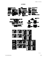
Page 25: ...YORK INTERNATIONAL 25 FORM 201 19 W3 1104 LEGEND LD010027...
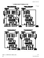
Page 26: ...YORK INTERNATIONAL 26 FORM 201 19 W3 1104 LD03282 LD03283 LD03284 035 15164 102 REV E...
Page 31: ...YORK INTERNATIONAL 31 FORM 201 19 W3 1104 NOTES...