

0171-971
2
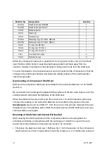
Position No.
Designation
Quantity
156 AA
Shaft seal cover SM/LM
1
156 AB
Shaft seal cover SF/LF
1
156 B
Balance piston
1
156 C
Slide ring
1
156 D
Sealing ring
1
156 EA
Retaining ring for 156 D, SM/LM
1
156 EB
Retaining ring for 156 D, SM/LF
1
156 F
O--ring, dia. 88.49 x
1
156 G
O--ring, dia. 107.54 x
1
156 H
O--ring, dia. 142.47 x
1
156 I
Countersunk screw
4
156 K
Cylinder screw
2
When the compressor has been in operation for a long period of time, the oil in the shaft
seal chamber, which helps to keep the shaft seal gas-tight, will drain away from the
chamber, making it possible for small amounts of refrigerant to leak from the shaft seal.
To avoid this situation, the enclosed seal set can be mounted in the compressor so that the
oil stays in the shaft seal chamber and keeps the sliding surfaces of the shaft seal lubri-
cated and gas-tight.
Dismounting of Compressor Shaft Seal
Dismount the compressor shaft seal as described in the
Instruction Manual, no. 0178-250,
Section 4.
Be very careful not to damage the lapped sliding surfaces of the two slide rings as even the
smallest scratch will reduce the tightness of the shaft seal.
When the shaft seal has been removed, the screws pos. 113 and the balance piston pos.
134 (see the drawing in the
Instruction Manual
) can be pulled out by means of the two
threaded pins no. 3,
part no. 3083-171, from the tool set. The pins are fastened in the two
threaded holes in the balance piston. Both the balance piston and the shaft seal cover pos.
165 must
not
be used again.
Mounting of Shaft Seal and Internal Oil Seal Set
After cleaning the shaft seal parts and the compressor shaft and checking them for
scratches and marks, oil all surfaces with the same type of oil which is used in the com-
pressor. Now the shaft seal and seal set are ready to be mounted.
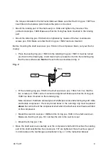
S
First place the balance piston pos. 156B (see fig. 1) from the seal set on the compressor
shaft and turn it so that it is possible to mount the screws pos. 113. Tighten the screws to


