background image

5285477-UIM-A-1016

14

Johnson Controls Unitary Products

Dehumidification/Humidity Switch Input

This model unit features a built in de-humidification feature for
advanced dehumidification during cooling operation. The unit indoor
blower control is designed to work with a humidity control that closes
when the humidity is below the set-point. The control is open when the
humidity is above the set-point. This humidity control may be referred to
as a humidistat or dehumidistat.

To use this feature, the control HUM STAT jumper must be set to YES
and a humidistat is connected from the low voltage R and HUM color
coded leads. During cooling operation if the humidity level is above the
humidistat set point, the indoor blower speed is reduced by approxi-
mately 15%.

Safety Controls

The control circuit includes the following safety controls:

High Pressure Switch (HPS) - 

The switch protects against excessive

discharge pressures and the defrost control locks out compressor oper-
ation.

Loss of Charge Switch (LCS) - 

The switch protects against loss of

charge due to a leak in the system. 

The above pressure switch is specifically designed to operate with R-
410A systems. R-22 pressure switches must not be used as replace-
ments for the R-410A pressure switches.

Indoor Circulating Blower 

When the thermostat calls for “FAN,” the thermostat terminal “G” is
energized signaling the indoor blower control board to operate the cir-
culating blower to run continuously. 

If a call for “COOL” occurs on “Y1,” the indoor blower runs at the “LOW
COOL” speed based on the “COOL” jumper setting. If a call for cool is
present on “Y1”+”Y2,” the indoor blower runs at the “HIGH COOL”
speed based on the “COOL” jumper setting.

If a call for “HEAT” occurs “W1” or “W1”+“W2”, the circulating blower
runs at the heat speed based on the “HEAT” jumper setting.

When the thermostat ends the call for “FAN,” the thermostat terminal
“G” is de-energized, and the indoor blower control board stops the cir-
culating blower operation.
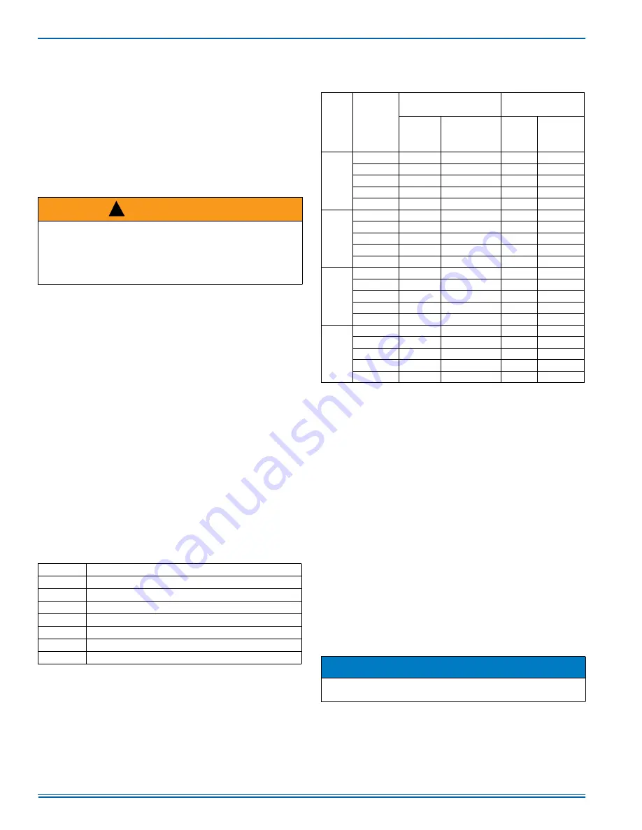
Delay Profiles

The Delay Profiles for each Delay jumper setting are shown in Table 16.
The levels shown in the Pre-Run, Short-Run, and Run Periods are a
percentage of the fan speed corresponding to the thermostat call. The
Post-Run and Off Delay levels are derived from the level of the previous
state, not the fan speed corresponding to the thermostat call. If in Delay
Profile B and in the Short-Run Period (82% of capacity) and the thermo-

stat call is removed, this causes control to enter the Post-Run state.
The Post-Run state level for Delay Profile B is 100% of the previous
level, so the level during the Post-Run state is 82%. 

HEATING SEQUENCE OF OPERATION

1.

On a call for heating, the thermostat sends 24 volts to “Y1” or
“Y1”+“Y2” on the defrost control board. After the anti-short cycle
period is complete, the 24 volt signal from “Y1” energizes contactor
coil “M” to supply power for the compressor and outdoor fan motor.
The indoor blower control operates the indoor blower motor at the
“LOW COOL” speed. If the 24 volt signal from “Y2” is present, the
defrost control board energizes the 2nd stage compressor solenoid
and signals the indoor blower control to operate the indoor blower
motor at the “HIGH COOL” speed. The reversing valve remains in
the heating position. Indoor blower speeds are selected by the
“COOL” jumper on the indoor blower control board.

2.

If the heat pump cannot meet the heating demand using mechanical
(compressor) heating, the indoor thermostat may energize axillary
(electric) heating to supplement the mechanical heating if an electric
heat kit was field installed. The room thermostat sends a 24 VAC sig-
nal on “W1” or “W1”+“W2.” The “W1” signal is received by the indoor
blower control board which then energizes the “HT1” output for elec-
tric heat. When a call for mechanical heating and supplemental heat-
ing is present, the indoor blower control operates the indoor blower at
either the “Y1”+”Y2” or the “W1” speed whichever is higher based on
the “COOL” and “HEAT” jumper selection.

A 2

nd

 stage auxiliary electric heating “W2” from the thermostat is to

be wired directly to the second stage heat kit input. 

 WARNING

The ability to properly perform maintenance on this equipment
requires certain expertise, mechanical skills, tools and equipment. If
you do not possess these, do not attempt to perform any mainte-
nance other than those procedures recommended in this Installation
Manual. Failure to heed this warning could result in serious injury
and possible damage to this equipment.

Table 15: 

Indoor Blower Control Fault Codes

Flashes

Fault Condition

LAMP OFF No Power to control

LAMP ON Internal control failure

SLOW RED Control normal operation

RAPID RED Test Mode

7 RED

Call for heat and cool at the same time

8 RED

Model ID plug not inserted

9 RED

Internal fault self corrected, attempting normal operation

!

TABLE 16 : Delay Profile Descriptions

Delay 

Profile

Period

Cooling

Heat Pump 

Heating

Level%

Time in State 

(Minutes)

Level%

Time in 

State 

(Minutes)

A

Pre-Run

Bypass

Bypass

Bypass

Bypass

Short-Run

Bypass

Bypass

Bypass

Bypass

Run

100

No Limit

100

No Limit

Post-Run*

100

1

100

.5

Off Delay*

Bypass

Bypass

Bypass

Bypass

B

Pre-Run

50

2

Bypass

Bypass

Short-Run

82

5

Bypass

Bypass

Run

100

No Limit

100

No Limit

Post-Run*

100

1

100

.5

Off Delay*

Bypass

Bypass

Bypass

Bypass

C

Pre-Run

Bypass

Bypass

Bypass

Bypass

Short-Run

Bypass

Bypass

Bypass

Bypass

Run

100

No Limit

100

No Limit

Post-Run*

100

1

100

.5

Off Delay*

50

1

Bypass

Bypass

D

Pre-Run

Bypass

Bypass

Bypass

Bypass

Short-Run

63

1.55

Bypass

Bypass

Run

100

No Limit

100

No Limit

Post-Run*

100

1

100

.5

Off Delay*

63

0.5

Bypass

Bypass

*The Post-Run and Off Delay levels are derived from the level of the 
previous state, not the fan speed corresponding to the thermostat 
call.

NOTICE

The “W1” must be energized with “W2” in order to enable indoor air
flow.

Summary of Contents for PHE6B36

Page 1: ...ERAL INFORMATION PHE units are factory assembled heat pumps designed for outdoor installation on a roof top or a slab Field installed optional electric heater accessories are available to provide supplemental electric heat com bined with electric cooling and heating The units are completely assembled on rigid removable base rails All piping refrigerant charge and electrical wiring is factory insta...

Page 2: ...tallation should be based on heat loss heat gain calculations made in accordance with industry recognized proce dures such as the Air Conditioning Contractors of America manual J CAUTION This product must be installed in strict compliance with the installa tion instructions and any applicable local state and national codes including but not limited to building electrical and mechanical codes WARNI...

Page 3: ...RESSOR INDOOR COIL REMOVABLE BASE RAILS COIL GUARD PANEL BLOWER MOTOR INDOOR BLOWER OPTIONAL ELECTRIC HEAT KIT TRANSFORMER CAPACITOR DEFROST CONTROL BOARD ECM BLOWER MOTOR CONTROL BOARD A0588 001 Table 1 Unit Limitations Model Unit Voltage Unit Limitations Applied Voltage Outdoor DB Temp Min Max Max F B36 208 230 3 60 187 252 125 B48 208 230 3 60 187 252 125 B60 208 230 3 60 187 252 125 ...

Page 4: ...n Rig the unit by attaching chain or cable slings to the lifting holes provided in the base rails Spreader bars whose length exceeds the largest dimension across the unit MUST be used across the top of the unit Units may be moved or lifted with a forklift Slotted openings in the base rails are provided for this purpose WARNING Do not attach supply and return duct work to the bottom of the unit bas...

Page 5: ...of supply air duct for the first 3 foot of duct for 20 25 kW zero inches there after For all other heaters zero inch clearance all sides for entire length of duct 36 Right Side 36 Side Opposite Ducts 36 Left Side 24 Duct Panel 0 Bottom 2 3 2 Units must be installed outdoors Over hanging structure or shrubs should not obscure outdoor air discharge outlet 3 Units may be installed on combustible floo...

Page 6: ...de the unit from production Field installation is required A filter rack and high velocity filters are standard on three phase units Filters must always be used and must be kept clean When filters become dirt laden insufficient air will be delivered by the blower decreasing your units efficiency and increasing operating costs and wear and tear on the unit and controls Filters should be checked mon...

Page 7: ...abinet must be provided with mechanical strain relief A fused disconnect switch should be field provided for the unit If any of the wire supplied with the unit must be replaced replacement wire must be of the type shown on the wiring diagram Electrical service must be sized properly to carry the load Each unit must be wired with a separate branch circuit fed directly from the main distribution pan...

Page 8: ...he unit is to be installed with a field installed single point power modification Breakers for heaters are included in the 20kW and 25kW heater kits 1 Minimum Circuit Ampacity 2 Maximum Over Current Protection per standard UL 1995 3 Fuse or HACR circuit breaker size to be field installed Table 6 Electrical Data For 208 3 60 Multi Source Power Model Compressor OD Fan Motor Blower Motor Electric Hea...

Page 9: ...unit is to be installed with a field installed single point power modification Breakers for heaters are included in the 20kW and 25kW heater kits 1 Minimum Circuit Ampacity 2 Maximum Over Current Protection per standard UL 1995 3 Fuse or HACR circuit breaker size to be field installed Table 8 Electrical Data For 230 3 60 Multi Source Power Model Compressor OD Fan Motor Blower Motor Electric Heat O...

Page 10: ...22 22 22 Tube diameter 3 8 3 8 3 8 Circuitry Type Interlaced Interlaced Interlaced Refrigerant control TXV TXV TXV Table 10 Continued on next page Indoor Coil Data Face area Sq Ft 6 3 6 3 6 3 Rows 3 3 4 Fins per inch 16 16 16 Tube diameter 3 8 3 8 3 8 Circuitry Type Interlaced Interlaced Interlaced Refrigerant control TXV TXV TXV Outdoor Fan Data Fan diameter Inch 26 26 26 Type Prop Prop Prop Driv...

Page 11: ...ing refrigerant leaks replacing refrigerant components such as filter drier pressure switch metering device or coil Units are shipped with compressor mountings which are factory adjusted and ready for operation CAUTION This system uses R 410A refrigerant which operates at higher pres sures than R 22 No other refrigerant may be used in this system CAUTION Scroll compressors require proper rotation ...

Page 12: ...ectric Heat A 1190 1133 1079 1026 953 861 798 742 689 638 B 1112 1054 991 928 840 760 701 648 591 532 C 955 886 821 721 642 584 508 453 391 324 D 856 776 708 591 516 459 375 321 262 191 PHE6B48 High Cool Heat A 1851 1809 1781 1746 1707 1656 1609 1552 1518 1460 B 1689 1652 1630 1597 1556 1504 1461 1404 1368 1310 C 1614 1578 1554 1520 1477 1424 1382 1324 1286 1228 D 1374 1333 1298 1255 1204 1145 110...

Page 13: ...t it energizes the reversing valve only 2 When the demand for cooling has been satisfied the 24 volt Y signal is removed and the contactor is de energized The indoor blower motor continues to run and ramps down after a 60 second delay Table 11 Electric Heat Multipliers Voltage kW Capacity Multipliers 1 Nominal Applied 240 208 0 75 230 0 92 1 Electric heaters are rated at nominal voltage Use this t...

Page 14: ...lt signal from Y1 energizes contactor coil M to supply power for the compressor and outdoor fan motor The indoor blower control operates the indoor blower motor at the LOW COOL speed If the 24 volt signal from Y2 is present the defrost control board energizes the 2nd stage compressor solenoid and signals the indoor blower control to operate the indoor blower motor at the HIGH COOL speed The revers...

Page 15: ...us defrost After the 40 minute inhibit time has expired temperature conditions must call for defrost continuously for 4 1 2 minutes before a defrost cycle is initiated A temperature inhibit feature prohibits defrost if the coil temperature is above 40 F A forced defrost feature puts the system into a defrost period every 6 hours and 4 minutes of accumulated compressor run time to recirculate lubri...

Page 16: ...e LAST ERROR button on the con trol board Table 19 shows the LED display representation for specified faults For instance a red LED display of 10 flashes indicates a control failure When any fault code is present the control does not display the current status code for the stage of operation Electric Heat Limit Switch Operation The 6HK single phase heat kits utilize a normally closed line voltage ...

Page 17: ...door blower instant on Electric heat stages on if so equipped OFF Electric heat stages off if so equipped Indoor blower off after off delay G W ON Indoor blower instant on in heating speed Electric heat stages on if so equipped W OFF Electric heat stages off if so equipped Indoor blower switches to continuous fan speed G Y ON Outdoor fan instant on Indoor blower instant on in cooling speed Compres...

Page 18: ...er to the unit is shut off prior to cleaning TROUBLESHOOTING WARNING Prior to any of the following maintenance procedures shut off all power to the unit to avoid personal injury NOTICE DO NOT use a pressure washer as coil fin damage will occur CAUTION Exercise care when cleaning the coil so that the coil fins are not dam aged Do not permit the hot outdoor air discharge to be obstructed by over han...

Page 19: ...PHASE SUPPLY Demand Defrost Control Fault Codes LAMP OFF STEADY RED SLOW RED RAPID RED 2 RED 3 RED 4 RED 5 RED 6 RED 7 RED 8 RED 9 RED 10 RED No Power to control Compressor operation active Compressor contactor energized Control normal operation No call for compressor Control normal operation ASCD Anti Short Cycle Delay active High Pressure Switch fault Not yet in lockout System in high pressure s...

Page 20: ...HED FOLLOWING CITY LOCAL AND OR NATIONAL CODES IN EFFECT AT THE TIME OF UNIT INSTALLATION 2 CAUTION LABEL ALL WIRES PRIOR TO DISCONNECTION WHEN SERVICING CONTROLS WIRING ERRORS CAN CAUSE IMPROPER AND DANGEROUS OPERATION IF ANY OF THE WIRING AS SUPPLIED WITH UNIT MUST BE REMOVED IT MUST BE REPLACED WITH TYPE 105 C 600 VOLT WIRE OR EQUIVALENT AND CLEARLY RENUMBERED FOR IDENTIFICATION VERIFY PROPER O...

Page 21: ...y Manifold sets must be at least 700 psig high side and 180 psig low side with 550 psig retard All hoses must have a service pressure rating of 800 psig Leak detectors must be designed to detect HFC refrigerants Systems must be charged with liquid refrigerant Use a commercial type metering device in the manifold hose R 410A can only be used with POE type oils POE type oils rapidly absorb moisture ...

Page 22: ...5285477 UIM A 1016 22 Johnson Controls Unitary Products NOTES ...

Page 23: ...s AC 230 volt AC 460 volts AC 575 volts AC Anti recycle timer Measured voltage L1 to L2 L2 to L3 L1 to L3 Total amperes L1 L2 L3 Compressor amperes L1 L2 L3 Measured voltage R and C outdoor unit control board Air Flow Setup Supply static inches of water column Supply air dry bulb temperature Return air dry bulb temperature Temperature drop 1 2 3 4 5 Low Medium Low Medium Medium High High A B C D O...

Page 24: ...er s manual Explain thermostat use and programming if applicable to owner Unit Operation and Cycle Test Operate the unit through continuous fan cycles from the thermostat noting and correcting any problems Operate the unit through cooling cycles from the thermostat noting and correcting any problems Operate the unit through mechanical heating cycles from the thermostat noting and correcting any pr...

Reviews: