035-17477-001 Rev. A (801)
Unitary Products Group
17
VENTING MULTIPLE UNITS
Each unit must have its own intake/vent piping and termina-
tion. Do not use common pipes for combustion air or venting.
The vent terminals must be located as shown in Figure 22 or
Figure 23.
PIPING ASSEMBLY
The final assembly procedure for the vent/combustion air pip-
ing is as follows:
1.
Cut piping to the proper length, beginning at the furnace.
2.
Deburr the piping inside and outside.
3.
Chamfer the outer edges of the piping.
4.
Dry-fit the entire vent/combustion air piping assembly.
5.
Disassemble the piping and apply cement primer and
cement per the cement manufacturer's instructions.
Primer and cement must conform to ASTM D2564 for
PVC, or ASTM D2235 for ABS piping.
FIGURE 19 :
Horizontal Termination Raised
Configuration for Additional Clearance
FIGURE 20 :
Horizontal Termination Configuration with Hori-
zontal Extension
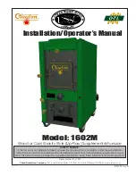
FIGURE 21 :
Vertical Termination
OVERHANG
12” MINIMUM
VENT
MAINTAIN 12” CLEARANCE ABOVE
HIGHEST ANTICIPATED SNOW LEVEL
OR GRADE WHICHEVER IS GREATER
12 SEPARATION BETWEEN
BOTTOM OF COMBUSTION AIR
AND BOTTOM OF VENT
COMBUSTION AIR
90°
OVERHANG
12” MINIMUM
VENT
MAINTAIN 12” CLEARANCE ABOVE
HIGHEST ANTICIPATED SNOW LEVEL
OR GRADE WHICHEVER IS GREATER
12 SEPARATION BETWEEN
BOTTOM OF COMBUSTION AIR
AND BOTTOM OF VENT
COMBUSTION AIR
90°
18” MAX.
MAINTAIN 12” MINIMUM
CLEARANCEABOVE HIGHEST
ANTICIPATED SNOWLEVEL.
MAXIMUM OF 24” ABOVE ROOF.
VENT
COMBUSTION AIR
12” VERTICAL SEPARATION
BETWEEN COMBUSTION
AIR AND VENT
FIGURE 22 :
Double Sidewall Termination
FIGURE 23 :
Double Rooftop Termination
VENT
COMBUSTION AIR
2”
6”