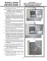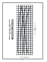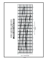
panels. Intake pressure drop will be read on one side of the
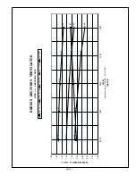
UERV, exhaust on the other side. Refer to blower
performance Tables showing specific air volumes at
various speeds. The table is for balanced air flows (fresh
air and exhaust air are equal), unbalanced airflow will
effect UERV performance.
1- Disconnect main power to unit before making
adjustment to economizer and/or UERV unit.
2- Replace UERV control access cover.
3- Set thermostat to normal operating position.
4- Restore power to unit.
X -
Maintenance
1- All motors use prelubricated sealed bearings; no further
lubrication is necessary.
2-Make visual inspection of dampers, linkage assemblies
and UERV rotating bearings during routine
maintenance. Filters should be checked periodically
and cleaned when necessary. Filter is located in fresh
air hoods.
DO NOT
replace permanent filters with
throwaway type filters.
3-Annual inspection of the self cleaning wheel is
recommended. With power disconnected, remove
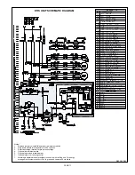
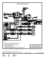
UERV access panels (rear) and unplug [J150 & P150]
(Refer to wiring diagram in this instruction manual).
Remove media and wash with water and/or mild
detergent. Replace media by reversing the above
procedure.
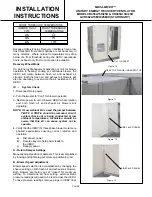
4-To install wheel segments follow steps A through E .
See
Figure 16. Reverse procedure for segment
removal.
A- Unlock two segment retainers (one on each side of the
selected segment opening.
B- With the embedded stiffener facing the motor side,
insert the nose of the segment between the hub plates.
C- Holding segment by the two outer corners, press the
segment towards the center of the wheel and inwards
against the spoke flanges. If hand pressure does not
fully seat the segment, insert the flat tip of a screw driver
between the wheel rim and outer corners of the
segment and apply downward force while guiding the
segment into place.
D- Close and latch each segment retainer under segment
retaining catch.
E- Slowly rotate the wheel 180
o
. Install the second
segment opposite the first for counterbalance. Rotate
the two installed segment 90
o
to balance the wheel
while the third segment is installed. Rotate the wheel
180
o
again to install the fourth segment. Repeat this
sequence with the remaining four segments.
PAGE 6
MAXA-MI$ER™
UNITARY ENERGY RECOVERY VENTILATOR
MODEL VR036A15H/25H & VR046A15H/25H
& VR062A15M/H/25M/H (STATIONARY)
INSTALLATION
INSTRUCTIONS
B
C
A
D
E
D
HUB
SEGMENT
FIGURE 16
SPOKE
SEGMENT RETAINER CATCH
WHEEL RIM
SEGMENT RETAINER
Figure 14
Figure 15
DELTA PRESSURE
(EXHAUST AIR)
FUSE BLOCK
Summary of Contents for MAXA-MISER VR036A15H
Page 10: ...PAGE 10 ...


