


105561-UIM-B-0605
Unitary Products Group
5
If a matching cooling coil is used, it may be placed directly on the fur-
nace outlet and sealed to prevent leakage. Follow the coil instructions
for installing the supply plenum. On all installations without a coil, a
removable access panel is recommended in the outlet duct such that
smoke or reflected light would be observable inside the casing to indi-
cate the presence of leaks in the heat exchanger. This access cover
shall be attached in such a manner as to prevent leaks.
RESIDENTIAL AND NON HUD MODULAR HOME
RETURN PLENUM CONNECTION
Return air may enter the furnace through the side(s) or bottom depend-
ing on the type of application. Return air may not be connected into the
rear panel of the unit. In order to stay within the velocity rating of the fil-
ter(s), it is recommended that applications over 1800 CFM (57 m³/min)
use return air from two sides, one side and the bottom or bottom only.
For single return application, see data and notes on blower perfor-
mance data tables in this manual.
BOTTOM RETURN AND ATTIC INSTALLATIONS
Bottom return applications normally pull return air through a base plat-
form or return air plenum. Be sure the return platform structure or return
air plenum is suitable to support the weight of the furnace.
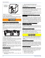
The furnace base is equipped with a rectangular blockoff panel that can
be removed by performing the following steps:
1.
Lay the furnace on its back.
2.
Remove the toe plate. See Figure 2.
3.
Slide the blockoff panel out and then replace the toe plate.
4.
Bend the 3/4” flanges that will be used to attach the return air ple-
num using the scribe marks in the furnace base. Refer to Figure 1
“Bottom Image Return End”.
5.
Be sure to seal the furnace to plenum connections to prevent air
leakage. Refer to Figure 1 for unit and plenum dimensions.
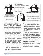
Attic installations must meet all minimum clearances to combustibles
and have floor support with required service accessibility.
The supply air temperature MUST NEVER exceed the Maximum
Supply Air Temperature, specified on the nameplate.
Operating the furnace above the maximum supply air temperature
will cause the heat exchanger to overheat, causing premature heat
exchanger failure. Improper duct sizing, dirty air filters, incorrect
manifold pressure, incorrect gas orifice and/or a faulty limit switch
can cause the furnace to operate above the maximum supply air
temperature. Refer to sections II and III for additional information on
correcting the problem.
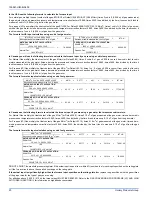
FIGURE 1: Dimensions
30-7/8
21-1/2
13-7/8
7
11
7/8
23-3/4
7/8
28-1/2
26-1/2
24-5/8
A
40
26-1/2
25-3/8
28-3/8
21-1/2
11
8
26-3/4
1-3/8
1-1/4
C
24-3/8
20
5/8
5/8
B
24-7/16
2
D
1-1/2” GAS
PIPE ENTRY
7/8” JUNCTION
BOX HOLE
T-STAT WIRING
7/8” K.O.
CONDENSATE
DRAIN 7/8” K.O.
OPTIONAL RETURN AIR
CUT-OUT (either side)
FOR USE WITH
EXTERNAL FILTER
FRAME
LEFT SIDE
FRONT
RIGHT SIDE
BOTTOM IMAGE
RETURN END
TOP IMAGE
SUPPLY END
1-1/2” GAS
PIPE ENTRY
7/8” JUNCTION
BOX HOLE
T-STAT WIRING
7/8” K.O.
CONDENSATE
DRAIN 7/8” K.O.
BTUH (kW)
Input/Output
Nominal CFM
(m
3
/min)
Cabinet
Size
Cabinet Dimension
Air Intake
A (in.)
A (cm)
B (in.)
B (cm)
C (in.)
C (cm)
D (in.)
D (cm)
40/38 (11.7/10.8)
1200 (34)
A
14-1/2
36.8
13-1/4
33.7
12-1/8
30.8
6-1/4
15.9
60/56 (17.6/16.1)
1200 (34)
B
17-1/2
44.4
16-1/4
41.3
15-1/8
38.4
8-1/2
21.6
80/74 (23.4/22.0)
1200 (34)
B
17-1/2
44.4
16-1/4
41.3
15-1/8
38.4
8-1/2
21.6
80/75 (23.4/22.0)
1600 (45)
C
21
53.3
19-3/4
50.2
18-1/2
47.0
8-7/8
22.5
80/75 (23.4/22.0)
2000 (57)
C
21
53.3
19-3/4
50.2
18-1/2
47.0
8-7/8
22.5
100/93 (29.3/27.8)
1600 (45)
C
21
53.3
19-3/4
50.2
18-1/2
47.0
8-7/8
22.5
100/93 (29.3/27.8)
2000 (57)
C
21
53.3
19-3/4
50.2
18-1/2
47.0
8-7/8
22.5
120/112 (35.1/32.8)
2000 (57)
D
24-1/2
62.2
23-1/4
59.4
21-7/8
55.6
10-5/8
27.0
135/127 (39.6/36.9)
2000 (57)
D
24-1/2
62.2
23-1/4
59.4
21-7/8
55.6
10-5/8
27.0


