background image

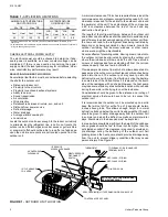
CAUTION: If the valve stem is backed out beyond the retaining

ring, system pressure could force the stem out of
the valve body and possibly cause personal injury.
In the event that the retaining ring is missing do not
attempt to open the valve.

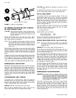
Some units may have factory installed 1-1/8" ball valves. To
open the valve, remove the brass valve stem cap, located on
the side of the valve, with an adjustable wrench. Next, turn the
valve stem 1/4 turn CCW (away from unit).

All caps must be replaced to prevent leaks.

Replace valve cap finger tight, then tighten an additional 

1

6

 of

a turn with a wrench, using a back-up wrench on the valve body.

WARNING:Do not under any circumstance connect refrigera-

tion gauges or refrigerant cylinders to the vapor line
service valve (large) gauge port. Personal injury
could result if the system is operating in the heating
mode. When checking pressures use the gauge
port located on the liquid service valve and the
gauge port located to the right of the vapor line
service valve.

OIL TRAPPING

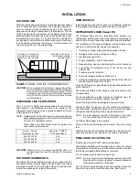
When the outdoor unit is above the indoor coil oil trapping is
necessary. Please refer to APPLICATION DATA, 690.01-AD1V
(1296) and worksheet 690.01-AD1.1V (791) "General Piping
Recommendations and Refrigerant Line Length".

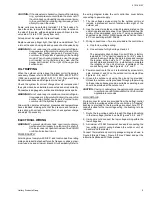
Check the system for correct charge after all components of
the system have been installed, connected and wired correctly.

Connect service gauges to suction and discharge service ports.

WARNING:Do not under any circumstance connect refrigera-

tion gauges or refrigerant cylinders to the vapor line
service value (large) gauge port. Personal injury
could result if the system is operating.

Allow unit to operate until system pressures and temperatures
have stabilized, making sure that the pressure and tempera-
tures align with unit service data. If not, check system charge
and adjust if necessary. 

ELECTRICAL WIRING

WARNING:To prevent electrical shock, open remote discon-

nect so electrical supply to outdoor unit is shut off.
Contactor does not open both sides of the 208/230
or 460 volt electrical circuit.

POWER SUPPLY

All wiring must comply with N.E.C. and local codes. See rating
plate and product data sheet for volts, frequency, phase, maxi-
mum fuse size and minimum branch circuit ampacity. Refer to

the wiring diagram inside the unit control box cover before
connecting to power supply.

1. The line voltage service wiring for the outdoor unit must

include a disconnect switch located within sight of the
outdoor unit.

2. Use the correct size fuse or circuit breaker as listed on the

unit rating plate and data sheet. See Tabular Data Sheet for
minimum recommended wire size. If using nonmetallic-
sheathed cable (NM or NM-B) ampacities shall be that of
60°C conductors per NEC 336-26.

3.  Wiring connections. —Two are provided in the control box:

a.  One for low voltage wiring.

b.  One entrance for high voltage Ll and L2

The adjustable High Voltage Conduit Plate is factory
installed for 1/2" conduit connections. For 3/4" conduit,
remove the screw holding the plate in place and reverse
the location of the holes. For 1" conduit, remove the
conduit plate and discard. Re - install screw to maintain
the integrity of the unit structure, regardless of the
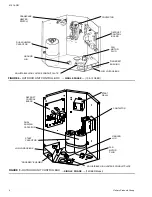
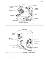
conduit being used. See Figures 4, 5, 6  and 7.

4. Power connection to the unit is facilitated by screw termi-

nals, marked Ll  and L2 on the outdoor unit contactor. See
Figures 4, 5, 6  and 7.  

 5.  Ground the outdoor unit using the ground lug provided.

Unless the outdoor unit is grounded through proper wiring
to the service entrance ground, a suitable separate ground
should be provided at the outdoor unit.

CAUTION: Casing or cabinet must be permanently grounded

in accordance with National Electric Code or other
applicable local codes.

LOW VOLTAGE

Pig-tail connector wires are provided from the defrost control
board to the low voltage section of the control box. A "fingered"
bushing is provided in the low voltage knockout hole. If 1/2"
conduit is used for the low voltage wiring, the bushing is to be
removed.

1.  Route the low voltage cable through the fingered bushing

in the low voltage junction box. See Figures 4, 5, 6  and 7.

2.  Using wire nuts, connect the low voltage wiring within the

low voltage box.

3.  A minimum of 19 AWG wire must be used in connecting the

low voltage control wiring between the outdoor unit, air
handler and thermostat.

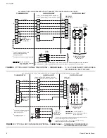
Connect thermostat and control package wiring as shown in
Figure 8 (Single Phase), Figure 9 (Three Phase) and per the
instructions packed with those pieces.

515.16-N3Y

Unitary Products Group

5

Summary of Contents for E1RA Series

Page 1: ...or in the Directory of Certified Unitary Heat Pumps published by the Air Conditioning and Refrigeration Institute Using unmatched com ponents may not only affect the performance of the system but may also void the warranty of the equipment Do not install any coil in a furnace which is to be operated during the heating season without attaching the refrigerant lines to the coil Allow ing the coil ch...

Page 2: ...due to wind chill effect Provide ample clearance from shrubs to allow adequate air to pass across the outdoor coil without leaves or branches being pulled into the coil The outdoor unit may never go into the defrost cycle even with minor frost build up during the daytime in some areas of the United States if it is placed on the south side of the residence with no shade However the heat pump may lo...

Page 3: ...ubing must be done with care to obtain reliable trouble free operation 1 Selection of proper refrigerant tubing grade and size 2 Refrigerant line routing cutting and fitting 3 Insulating the vapor line 4 Proper preparation of joint connections 5 Reassembling cleaning and brazing the joint connections 6 Connecting the refrigerant lines to the indoor coil and outdoor unit 7 Pressure leak test all jo...

Page 4: ... Recommendations and Refrigerant Line Length for vapor and liquid line sizing cali bration of liquid line pressure loss or gain determination of vapor line velocity elevation limitations orifice connections system charging traps etc Total line lengths are limited to 75 feet due to the storage capacity of the accumulator Systems with total line lengths over 50 feet must be provided with 1 Low Volta...

Page 5: ...t for volts frequency phase maxi mum fuse size and minimum branch circuit ampacity Refer to the wiring diagram inside the unit control box cover before connecting to power supply 1 The line voltage service wiring for the outdoor unit must include a disconnect switch located within sight of the outdoor unit 2 Use the correct size fuse or circuit breaker as listed on the unit rating plate and data s...

Page 6: ...LTAGE BOX FAN MOTOR PLUG FIGURE 4 OUTDOOR UNIT CONTROL BOX SINGLE PHASE 10 12 SEER CONTACTOR DUAL RUN FAN CAPACITOR GROUND LUG ADJUSTABLE HIGH VOLTAGE CONDUIT PLATE DEFROST CONTROL BOARD FINGERED BUSHING LOW VOLTAGE BOX FAN MOTOR PLUG START RELAY START CAPACITOR FIGURE 5 OUTDOOR UNIT CONTROL BOX SINGLE PHASE 14 SEER Model 515 16 N3Y 6 Unitary Products Group ...

Page 7: ...FIGURE 6 OUTDOOR UNIT CONTROL BOX THREE PHASE 10 SEER 036 and 048 Models FIGURE 7 OUTDOOR UNIT CONTROL BOX THREE PHASE 10 SEER 060 Model 515 16 N3Y Unitary Products Group 7 ...

Page 8: ...T D O O R U N I T T H E R M O S T A T I N D O O R U N I T P O W E R W I R I N G 2 0 8 2 3 0 3 6 0 4 6 0 3 6 0 P O W E R W I R I N G 2 4 V C O N T R O L W I R I N G N E C C L A S S 2 L O W V O L T A G E T E R M I N A L B L O C K 3 4 I N A I R H A N D L E R W I T H E L E C T R I C H E A T 3 C h e c k t h e l o w v o l t a g e t e r m i n a l b l o c k o n t h e i n d o o r u n i t f o r t h e a c t ...

Page 9: ...EFROST SAFETY LOCKOUT MODE The lock out control opens the circuits to the compressor contactor stopping the compressor in response to 400 High Pressure limit switch opening for more than one second The compressor will remain off until the high pressure switch re closes During the period the switch is open the control will provide a pulsed output at the X terminal to indicate the lock out condition...

Page 10: ...ll remain in defrost until the defrost thermostat opens or 10 minutes expires If the thermostat is open when the short is removed the heat pump will exit defrost immediately 14 SEER WITH DEMAND DEFROST SAFETY LOCKOUT MODE The lock out control opens the circuits to the compressor contactor stopping the compressor in response to the high pressure 400 limit switch or the high discharge temperature sw...

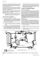
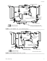
Page 11: ... DRYER solid core SHOWN IN COOLING POSITION ORIFICE heating FIGURE 13 FLOW DIAGRAM 060 10 12 SEER Single Phase INDOOR COIL COMPRESSOR 4 WAY REVERSING VALVE SUCTION ACCUMULATOR OUTDOOR COIL COOLING CYCLE FLOW HEATING CYCLE FLOW SHOWN IN COOLING POSITION FIELD CONNECTED LINE FIELD CONNECTED LINE LIQUID SENSOR Non Adjustable Thermal Expansion Valve Heating FILTER DRYER solid core Non Adjustable Therm...

Page 12: ...llow the unit to go into a defrost cycle if the compressor is operating When the short is removed the heat pump will remain in defrost until the coil temperature reaches 75 F or 14 minutes expires If the liquid coil temperature happens to be above 75 F the short must be maintained to keep the unit in a defrost cycle It should be used since the unit WILL REMAIN in defrost until the short is removed...

Reviews: