background image

66433-YIM-B-1004

18

Unitary Products Group

2.

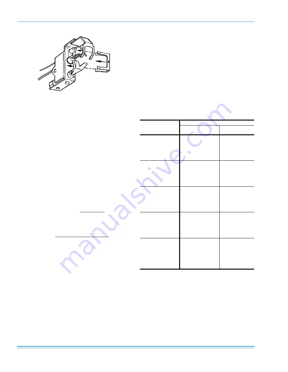
Lift the pilot and sensor from the assembly. Care must be 
taken not to damage the pilot or sensor when removing 
this assembly.

ADJUSTMENT OF TEMPERATURE RISE

After about 20 minutes of operation, determine the furnace
temperature rise. Take readings of both the return air and the
heated air in the ducts about six feet from the furnace where
they will not be affected by radiant heat.

The temperature rise (or temperature difference between the
return air and the heated air from the furnace) must lie within
the range shown on the rating plate and the data in Tables 3
and 4.

After the temperature rise has been determined, the CFM can
be calculated as follows:

DIRECT DRIVE BLOWER

All units have direct drive, constant CFM blower motors.
Refer to the Unit Wiring Diagram Table 1 for the desired cool-
ing CFM. Heating CFM is preset at the factory.

CHECKING GAS INPUT

NATURAL GAS

1.

Turn off all other gas appliances connected to the gas 
meter.

2.

With the furnace turned on, measure the time needed for 
one revolution of the hand on the smallest dial on the 
meter. A typical gas meter usually has a 1/2 or a 1 cubic 
foot test dial.

3.

Using the number of seconds for each revolution and the 
size of the test dial increment, find the cubic feet of gas 
consumed per hour from Table 11.

If the actual input is not within 5% of the furnace rating with
allowance being made for the permissible range of the regu-
lator setting, replace the orifice spuds with spuds of the
proper size.

NOTE:

To find the BTU input, multiply the number of cubic
feet of gas consumed per hour by the BTU content
of the gas in your particular locality. (Contact your
gas company for this information since it varies
widely from city to city.)

FIGURE 12 - IGNITOR AND FLAME SENSOR 

ASSEMBLY

Degrees F Temp Rise = 

BTUH Output

1.08 x CFM

OR

CFM = 

BTUH Output

1.08 x Degrees F Temp Rise

TABLE 11: GAS RATE - CUBIC FEET PER HOUR

1

1.

EXAMPLE

: By actual measurement, it takes 38 sec-

onds for the hand on the 1-cubic foot dial to make a 
revolution with just a 100,000 BTUH furnace running. 
Using this information, locate 38 seconds in the first 
column of Table 11. Read across to the column headed 
“1 Cubic Foot,” where you will see that 95 cubic feet of 
gas per hour are consumed by the furnace at that rate. 
Multiply 95 x 1050 (the BTU rating of the gas obtained 
from the local gas company). The result is 99,750 
BTUH, which is close to the 100,000 BTUH rating of 
the furnace.

SECONDS

FOR ONE

REV.

SIZE OF TEST DIAL

1/2 CU. FT.

1 CU. FT.

10

180

360

12

150

300

14

129

257

16

113

225

18

100

200

20

90

180

22

82

164

24

75

150

26

69

138

28

64

129

30

60

120

32

56

113

34

53

106

36

50

100

38

47

95

40

45

90

42

43

86

44

41

82

46

39

78

48

37

75

50

36

72

52

35

69

54

34

67

56

32

64

58

31

62

60

30

60

Summary of Contents for DNZ 060

Page 1: ...ords NOTE CAUTION and WARNING Notes are intended to clarify or make the installation easier Cautions are given to prevent equipment damage Warnings are given to alert installer that personal injury an...

Page 2: ...NPUT 18 NATURAL GAS 18 TROUBLESHOOTING 19 TYPICAL WIRING DIAGRAM NOTES SEE FIGURES 13 14 AND 15 23 LIST OF FIGURES Fig Pg 1 UNIT CENTER OF GRAVITY 5 2 FIELD WIRING DIAGRAM CONTROL WIRING 7 3 POWER WIR...

Page 3: ...e given to prevent equipment damage WARNINGS are given to alert the installer that personal injury and or equipment damage may result if installation procedure is not handled properly INSPECTION As so...

Page 4: ...hey are to be installed at the dealer s and or the customer s expense Size of unit for proposed installation should be based on heat loss heat gain calculations made in accordance with industry recogn...

Page 5: ...f sufficient length should be used across the top of the unit Units may also be moved or lifted with a fork lift Slotted openings in the skid are provided for this purpose Forks must pass completely t...

Page 6: ...sing your units efficiency and increasing operating costs and wear and tear on the unit and controls Filters should be checked monthly this is especially impor tant since this unit is used for both he...

Page 7: ...t be sized properly to carry the load Each unit must be wired with a separate branch circuit fed directly from the meter panel and properly fused Refer to Figure 3 for typical field wiring and to the...

Page 8: ...are factory adjusted and ready for operation PHASING Three phase scroll compressors operate in only one direc tion If the scroll is drawing low amperage has similar suction and discharge pressures or...

Page 9: ...own Continuous return air temperature should not be below 55 F TABLE 4 PROPANE1 LP GAS APPLICATION DATA AVAILABLE ON MODELS INPUT CAPACITY MBH 2 OUTPUT CAPACITY MBH GAS RATE 3 FT 3 HR NUMBER OF BURNER...

Page 10: ...l shut off valve may have to be installed outside of the unit 3 Use wrought iron or steel pipe for all gas lines Pipe dope should be applied sparingly to male threads only FIGURE 4 EXTERNAL SUPPLY CON...

Page 11: ...tened to the outside of the side gas control electri cal compartment with the screws provided in the bag attached to the inside of the gas control electrical compart ment see Figure 6 If flexible stai...

Page 12: ...TA MODEL DNZ POWER SUPPLY VOLTAGE LIMITATIONS1 COMPRESSOR COND FAN MOTOR FLA SUPPLY AIR BLOWER MOTOR FLA MINIMUM CIRCUIT AMPACITY MAX FUSE SIZE AMPS2 MAX HACR BREAKER SIZE AMPS UNIT POWER FACTOR TRANS...

Page 13: ...L All dimensions are in inches They are subject to change with out notice Certified dimensions will be provided upon request TABLE 9 UNIT DIMENSIONS FRONT UNIT SIZE DIMENSION A B 024 030 036 33 1 2 18...

Page 14: ...8 DIA KNOCKOUT 1 2 NPTI CONNECTION LOW VOLTAGE CONN DIA KNOCKOUT 8 7 FIGURE 8 UNIT DIMENSIONS BACK BOTTOM 1 3 4 1 5 2 9 9 1 6 1 5 3 1 2 1 3 4 1 3 4 1 5 4 1 4 1 2 3 1 2 3 3 8 1 4 1 2 2 8 3 8 1 4 1 2 C...

Page 15: ...utomatically The limit switch operates when a high temperature condition caused by inadequate supply air flow occurs thus shut ting down the ignition control and closing the main gas valve and energiz...

Page 16: ...rmostat to the desired setting 12 If the unit will not operate follow the instructions To Turn Off Gas To Appliance and call your service technician or gas supplier TO TURN OFF GAS TO UNIT 1 Set the t...

Page 17: ...lame 3 The pilot flame should envelope 3 8 of the end of the flame sensor and not contain any yellow color see Fig ure 11 4 Replace the pilot adjustment cover screw after the pilot flame is set To che...

Page 18: ...gas consumed per hour from Table 11 If the actual input is not within 5 of the furnace rating with allowance being made for the permissible range of the regu lator setting replace the orifice spuds wi...

Page 19: ...ECKOUT procedures Troubleshooting of components necessitates opening the electrical control box with the power connected to the unit Use extreme care when working with the live circuits Check the unit...

Page 20: ...66433 YIM B 1004 20 Unitary Products Group FIGURE 13 TYPICAL WIRING DIAGRAM DNZ 208 230 1 60...

Page 21: ...66433 YIM B 1004 Unitary Products Group 21 FIGURE 14 TYPICAL WIRING DIAGRAM DNZ 208 230 3 60...

Page 22: ...66433 YIM B 1004 22 Unitary Products Group FIGURE 15 TYPICAL WIRING DIAGRAM DNZ 460 3 60...

Page 23: ...Refrigerant operates at 50 70 percent higher pressures than R 22 Be sure that servicing equipment and replacement components are designed to operate with R 410A R 410A Refrigerant cylinders are rose c...

Page 24: ...e without notice Printed in U S A 66433 YIM B 1004 Copyright 2004 by Unitary Products Group All rights reserved Supersedes 66433 YIM A 0903 035 19532 000 A 0903 Unitary 5005 Norman Products York OK Gr...

Reviews: