JOHNSON CONTROLS
33
SECTION 2 - START-UP AND OPERATION
FORM 102.20-OM2
ISSUE DATE: 6/01/2015
2
Thermotech
®
Start-Up Procedure
1. Remove the belts from the motor sheave and ro-
tate the wheel a minimum of one full Revolution.
The seals are non-contact. If the wheel does not
rotate freely it may be due to the wheel being
in contact with the seal. If the wheel cannot be
turned by hand contact Thermotech.
For TC sizes 14-82. To remove the belt,
an idler pulley will need to be loosened.
2. The side seals should also be checked for clear-
ance to insure nothing has moved in shipping. If
the wheel is in contact with the aluminum encas-
ing the side seals, the wheel will need to be re-
centered in the casing. This is done by loosening
the bearing bolts and by using the bearing adjust-
ing bolts. Re-center the wheel insuring proper
side seal clearance. Re-tighten bearing bolts as
follows: 3/8 inch = 35 ft lbs., 1/2 inch = 45 ft. lbs.,
3/4 inch = 100 ft lbs.
3. Check to insure sheave/bushing is not rubbing on
the gear box.
4. At this point the wheel should rotate freely with
no drag or rubbing, with the exception of the riv-
ets at the hub cover. A slight rub here is accept-
able. Proper wheel rotation technique:
Rotate wheel by applying pressure to the rim not
the media. Care should be taken not to damage the
media face.
5. The seals are set at the factory and should not re-
quire adjustment. If the seals are rubbing on the
media face, due to installation or other factors,
the seals will need to be adjusted. First, rotate the
wheel one full revolution and determine where the
wheel media face is rubbing on the seal. Work-
ing on one seal quadrant at a time, loosen the seal
tek screws. Then, move the seal away from the
wheel surface until no more rubbing is noticed.
A typical large diameter wheel will have a flat
-
ness variation of 1/16” from the high to the low
point of the wheel surface. If the seals are adjusted
correctly, the seal gap will vary that much as the
wheel turns, but it should never be touching the
wheel surface.
6. If the unit is supplied with an adjustable purge,
determine the proper purge angle from the order-
ing code on the unit nameplate or the specific data
for your project. Insure proper purge angle set-
ting is correct by visual inspection. The minimum
purge angle is 1 degree. There are 10 adjustment
points in one degree increments.
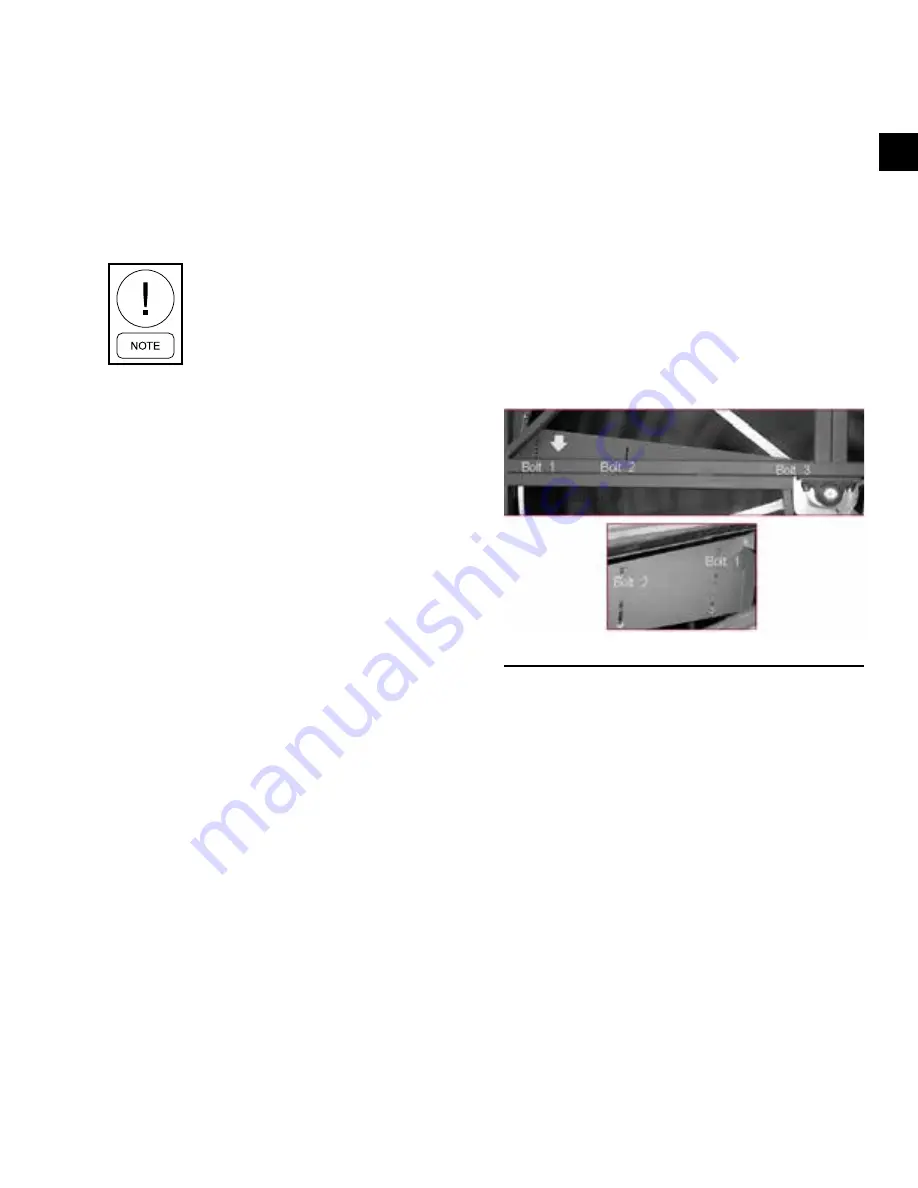
Purge Adjustment: TF Series Wheels
The purge angle can be adjusted with each purge set-
ting hole equal to one degree. The bolts that position
the purge angle are located on the backside of the purge
and are not visible. First loosen bolt 2 and 3. Then re-
move the bolt 1. The whole purge section is then mov-
able to a new location. Re-install bolt 1 in the new hole
location and re-tighten all the bolts.
FIGURE 26 -
PURGE ANGLE DETAIL
LD17222
Purge Adjustment: TC Series Wheels
The purge angle can be adjusted with each purge set-
ting hole equal to one degree. Bolt number 1 positions
the purge angle and is located on the front side of the
purge. Bolt number 2 is the pivot point and is located
on the inside of the frame and is not visible. First loos-
en bolt 2. Then remove bolt 1. The purge wiper section
is then movable to a new location. Re-install bolt 1 in
the new hole location and re-tighten all the bolts.
Purge angle detail showing bolt locations on front side
of purge. The purge wiper bolt 2 pivot point is slotted
so as the purge wiper is adjusted it can be moved so
that the outer edge of the seal is always in contact with
the main rotor seal.


