


4-3
IM 703753-01E
Troubleshooting and Maintenance
4
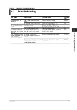
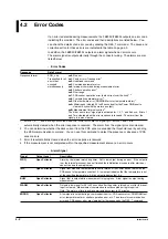
4.2 Error Codes
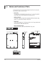
• Causes of Error Codes and Their Corrective Action
ERR_n
Error
Cause of Error
Corrective Action
n=1
Parity error
The communication interface may not be
Check the communication interface settings.
Framing error
configured correctly.
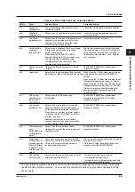
n=2
Undefined
Output when an undefined command is used.
Check the command again and send the
command error
correct command.
n=3
Command
Output when the contents of the parameters
Check the parameter contents.
parameter error
attached to the command are not correct.
Example) The value is outside the range,
or the character is inappropriate.
n=4
Uninterruptible
Output when a command that is not allowed
Wait for the measurement to finish and send
command
to interrupt a measurement is received
the command again. If the BPR command is
reception error
during measurement.
being executed, issue the STO command to
When executing BPM, BPR, or ZER.
terminate the measurement. Then, send the
Example) When the BPR command is sent
next command.
and measurement is being executed,
commands other than the STO or SRQ
command cannot be accepted.
n=5
Shutter operation
Output when the shutter does not operate
The FB200C/FB200L has malfunctioned.
error
correctly.
Request for repairs.
n=6
Upper limit
Output when the optical power level exceeds
When using the –5 dBm measurement range:
the maximum value of the measurement range. Decrease the input power to the FB200C/
FB200L.
When using the –15 dBm measurement range:
Change the measurement range to –5 dBm.
When using the –25 dBm measurement range:
Change the measurement range to –15 dBm.
If the error is output even after making the
change, decrease the input power to the
FB200C/FB200L.
n=7
*1
PDA sensor
Output when the PDA sensor has
The FB200C/FB200L has malfunctioned.
operation error
deteriorated.
Accurate measurement is not possible.
(dark current
Request for repairs.
over the limit)
n=8
Computation
Output when computation is not possible
The FB200C/FB200L has malfunctioned.
parameter error
using the specified computation sequence
Request for repairs.
for the specified measurement conditions.
When this error is output, an alarm signal is
output from pin No. 30 (ERROR pin) of the
interface connector.
Example) Computation is not possible
because the memory has been overwritten,
or the computed result is invalid.
n=9
Other hardware
Output when the temperature sensor
The FB200C/FB200L has malfunctioned.
error
malfunctions or when the memory does not
Request for repairs.
(ROM/RAM error
operate correctly.
or temperature
alarm)
n=A
Warming up
Commands are not received until the PDA
Wait at least 40 seconds after power on before
(cleared 30 to 40
sensor is controlled to a certain temperature.
sending the command.
seconds after the
This error is output when a command is
If this error is output even after 40 seconds
Power ON/Reset
received during this period.
elapses, restart the FB200C/FB200L.
is cleared in sync
with the warm up
output)
n=B
Measurement
Output when the computation does not finish
• Increase the measurement interval.
interval overrun
within the specified interval.
• Decrease the average count.
• Increase the serial communication baud rate.
• Set to a lower sensitivity range.
1 You can determine whether the dark current from the PDA sensor exceeded the threshold level by sending
the ZER communication command. You can use this command to detect the presence or absence of PDA
sensor errors.


