background image

11-9

IM AQ1300-01EN

VLAN T

est

3

2

1

4

5

6

7

8

9

10

11

12

13

14

App

Index

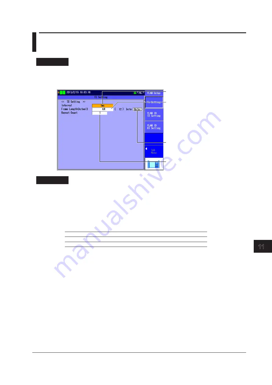
11.4  Configuring the Tx Settings

Procedure

TX Setting Screen

Follow the procedure in section 11.1 to display the VLAN Test Setup screen.
Press the 

Detail Setup

 soft key and then the 

TX Setting

 soft key to display the following screen.

Set the interval

(1ms, 10ms, 100ms, 1s).
Set the frame length (actual).

L2 and L3-IPv4

(VLAN 1 stack:  64 (68) to 9999 (9999) bytes

 VLAN 2 stacks:  64 (72) to 9999 (9999) bytes)

L3-IPv6

(VLAN 1 stack:   74 (78) to 9999 (9999) bytes

 VLAN 2 stacks:  74 (82) to 9999 (9999) bytes)

Refer to the frame length table. 

►section 4.5

Set the repeat count

(1-15).

Explanation

TX Setting Screen

Interval

  Set the Tx frame transmission interval.
  1ms, 10ms, 100ms, 1s

Frame Length (Actual)

  Set the frame length of Tx frames. The actual frame length of the specified frame is also displayed.

VLAN

L2 and L3-IPv4

L3-IPv6

1 stack

64 (68) to 9999 (9999) bytes

74 (78) to 9999 (9999) bytes

2 stacks

64 (72) to 9999 (9999) bytes

74 (82) to 9999 (9999) bytes

Frame Length Table

  You can refer to the frame length table to select the value.
  The table is created on the setup software. For details, see the Setup Software User’s Manual.

Repeat Count

  Set the number of times to transmit the VLAN ID group.
  Range:  1 to 15

Summary of Contents for AQ1300 Series

Page 1: ...User s Manual AQ1300 Series 1G 10G ETHERNET Multi Field Tester IM AQ1300 01EN 6th Edition...

Page 2: ...to AQ1300 Series 1G 10G ETHERNET Multi Field Testers with firmware version R1 10 01 001 and later If you are using an older version you will not be able to use all the features described in this manu...

Page 3: ...ii IM AQ1300 01EN Revisions 1st Edition November 2009 2nd Edition March 2010 3rd Edition October 2010 4th Edition June 2012 5th Edition March 2013 6th Edition June 2014...

Page 4: ...ment or user s data and precautions that can be taken to prevent such occurrences Note Calls attention to information that is important for proper operation of the instrument Symbols and Conventions U...

Page 5: ...16 RFC2544 Measurement AQ1300 Option 1 41 1 17 VLAN Test 1 48 1 18 Telnet Remote Control 1 49 1 19 E OAM Test 1 50 Chapter 2 Screen Explanations 2 1 Measurement Screens Common Items 2 1 2 2 Measureme...

Page 6: ...uring 7 1 Starting and Stopping Measurement 7 1 7 2 Performing L1 Control 7 8 7 3 Changing the Tx Rate 7 10 7 4 Inserting Errors 7 11 7 5 Performing a Traceroute Test 7 12 7 6 Displaying Test Results...

Page 7: ...ettings 11 9 11 5 Configuring the VLAN ID Tx Settings 11 10 11 6 Configuring the VLAN ID Rx Settings 11 14 11 7 Starting and Stopping Measurement 11 17 11 8 Switching Screens and Saving Measured Resul...

Page 8: ...USB Function 14 1 14 2 Setting the Date and Time 14 2 14 3 Configuring Power Save Settings 14 3 14 4 Configuring Network Settings 14 4 14 5 Resetting the AQ1300 Series to Its Factory Default Settings...

Page 9: ...tting configuration Result display Report output After loading a setup file begin measurement simply by pressing START You can also change the parameters based on the loaded settings AQ1300 Series AQ1...

Page 10: ...onfigure setup files and test items using the setup software which runs on Windows PC OPM AQ1300 Option Select OPM to measure optical input power using the optical power meter RFC2544 AQ1300 Option An...

Page 11: ...easurement traffic and measure the network QoS performance by defining a Tx frame with up to eight channels of QoS parameters and specifying the frame length and Tx rate The AQ1300 Series takes statis...

Page 12: ...device is set to Loopback Test mode so that the AQ1300 Series receives the traffic that it sends and the AQ1300 Series measures the network round trip latency Traffic Loopback MAC address DA SA switch...

Page 13: ...affic generation Interval 1 ms to 1 s Ping reply emulation Network Other device Traceroute Test You can also use traceroute testing to check the route to the target the other device Traceroute ICMP em...

Page 14: ...single person can perform this test Master Slave 3 Search response Search Slave 1 Slave 2 The master can control the slaves remotely through the measured connection Searching for slaves The AQ1300 can...

Page 15: ...mote fault signals The AQ1300 Series can transmit LF and RF signals consecutively start stop Also when Manual has been selected in the Test menu the AQ1300 Series can automatically send an RF signal u...

Page 16: ...detects and clears 66B Sync hi ber on the basis of the following conditions when signal reception is in a sync block lock state as defined in IEEE802 3 This feature is supported in firmware version FW...

Page 17: ...at Constant When the traffic format is Constant frames are sent continuously at a constant interval You can change the interframe gap IFG by changing the Tx rate Frame Preamble Data FCS Frame Frame Fr...

Page 18: ...tages when Auto or Auto Remote has been selected in the Test menu Note When the you set the Tx rate in bits specify the number of bits in the IFG In QoS Test Mode Regardless of the Test menu you can o...

Page 19: ...0 7 VLAN 1 2 CFI 0 1 VLAN 1 2 VLANID 0 4095 IPv4 Destination address Manual the same as Destination Setting Address value format Source address Manual the same as Source Setting Address value format T...

Page 20: ...es Variable Field You can change the specified field when Manual has been selected in the Test menu and the test mode is Traffic Test There are two methods for changing a field field specification in...

Page 21: ...Tag field length in units of 2 bytes for expansion Timestamp The timestamp time data is inserted into a 32 bit field in the test tag If the other device is in Loopback Test mode you can use the timest...

Page 22: ...ames separately When Auto or Auto Remote has been selected in the Test menu and the test mode is QoS test you can specify different QoS values frame lengths and transfer rates for each channel and sen...

Page 23: ...priority control of a network device The QoS filter operates on the frames that pass through the base filters You can use the QoS filter when Manual has been selected in the Test menu and the test mod...

Page 24: ...received frames that have been received again Sequence Error Detection Examples Loss Packet Frames that were sent but not received are counted as loss packets The Loss Packet number represents the to...

Page 25: ...icate packets 1 2 3 4 5 6 8 9 10 12 13 14 15 16 20 Wrong order 4 Loss Packet 1 Max Burst Loss 1 Reorder Packet 4 Duplicate Packet 1 18 19 17 7 11 21 22 Duplicate 1 Loss 1 Duplicate Packet Frames that...

Page 26: ...ayload Condition for Sync Loss A synchronized state changes to a sync loss state when an error of 50 bits or more is detected within 128 bits Note The bytes that undergo BER measurement include the fi...

Page 27: ...nt 16 digit integer 66B sync hi ber count 16 digit integer Tx Frame 16 digit integer Byte 16 digit integer Rate 5 digits after the decimal point Rate fps 10 digit integer Rate Bps 10 digit integer Rat...

Page 28: ...its after the decimal point Peak Rate fps 10 digit integer Peak Rate bps 10 digit integer Average Rate 5 digits after the decimal point Average Rate fps 10 digit integer Average Rate bps 10 digit inte...

Page 29: ...ount 16 digit integer Mismerge count 16 digit integer Unexpected MEG Level count 16 digit integer Unexpected Period count 16 digit integer Link Down Count 16 digit integer CRC Error 16 digit integer U...

Page 30: ...sync header 2 bits is 00 or 11 when signal reception is in a sync block lock state as defined in IEEE802 3 This feature is supported in firmware version FW Ver R1 08 01 001 and later 66B Sync hi ber C...

Page 31: ...te Indicates the data reception rate as a percentage Rate fps Indicates the number of frames that have been received normally in a single second Rate Bps Indicates the number of bytes in the frames th...

Page 32: ...set for VLAN stacks in the source settings 4 bytes are considered oversized Alignment Error Indicates the number of alignment error frames An error occurs when a received frame s length is not in uni...

Page 33: ...ed in the received payloads Payload error detection is enabled when at least one sequence measurement source frame is received The AQ1300 Series detects errors by comparing the CRC values calculated f...

Page 34: ...a frame s timestamp and the time that it was received Avg Latency us For each QoS channel this item indicates the average difference between a frame s timestamp and the time that it was received Loss...

Page 35: ...when the AQ1300 Series synchronizes with the received frame at least once when the BERT target byte is not zero BERT Target Byte Indicates the number of synchronized bytes that have been received Bit...

Page 36: ...een received Undersize Error Indicates the number of undersize frames less than 64 bytes that have been received Alignment Error Indicates the number of alignment error frames that have been received...

Page 37: ...the domain name is not Unexpected MEG Level Count Indicates the number of unexpected MEG level detections This is detected when the maintenance domain level in the received CCM frame is less than the...

Page 38: ...he oversize threshold ARP requests with three or more VLAN stacks VLAN Tag Handling The AQ1300 Series sends ARP replies in response to ARP requests with VLAN tags attached ARP Requests with Test Tags...

Page 39: ...he transmission of the current ping reply has finished If a linkdown occurs immediately after a ping request is received the AQ1300 Series will not send a reply to that request Automatic MAC Address A...

Page 40: ...eighbor Discovery Protocol replying the AQ1300 Series resolves the address by sending an NA Neighbor Advertisement when it receives an NS Neighbor Solicitation When you enable NDP it is always enabled...

Page 41: ...n response to the following kinds of ping6 requests Ping6 requests with an LLC SNAP header attached only ping6 requests that conform to the DIX specification are supported Fragmented ping6 requests Pi...

Page 42: ...NDP In automatic MAC address acquisition through NDP the AQ1300 Series uses NDP neighbor discovery protocol message processing at the start of testing to automatically obtain the MAC address of the I...

Page 43: ...84 up to two VLAN stacks to 9999 bytes Unsupported Ping Frames IEEE802 3 ping frames Fragmented ping frames Ping frames with an MPLS label attached Ping frames with three or more VLAN stacks Tracerout...

Page 44: ...to 4 hours 14400 seconds or select 12 24 48 or 72 hours End settings Stop Overwrite Maximum number of log items 4 End Setting Description Stop Logging stops after the logging time has passed Overwrit...

Page 45: ...eferred to as test items You can configure test items using the setup software You can save up to eight test modes test items to a single test scenario file You can execute tests by loading the setup...

Page 46: ...fail results of measurement You can set the pass fail conditions in the setup software for each test mode You can only use the AQ1300 Series to display the pass fail conditions not to set them You can...

Page 47: ...h 12 measurement setup files each The management file name is fixed at disManage dmf Statistical Result File A file of the measured results or the measured statistical results You can save the results...

Page 48: ...Reference You can make the displayed measured value the reference and display subsequent measured values as relative values Zero Set You can adjust the internal deviation of the optical power measurem...

Page 49: ...AQ1300 Series performs another measurement to detect whether a loss occurs at this new rate If a loss is detected the same operations are repeated These operations are repeated until the rate is decre...

Page 50: ...at is used to converge the throughput measurement When the difference between the rates when a loss was detected and when no losses were detected falls within the resolution range the AQ1300 Series co...

Page 51: ...ut Through Method The time from when the first bit of the frame signal is received at the input port to when the first bit of the frame signal is transmitted from the output port is measured as the de...

Page 52: ...nput frames number of output frames Number of input frames 100 Test Duration This is the time that frame signals are transmitted for during a frame loss rate measurement at a single rate Number of Tri...

Page 53: ...ies of operations from the start of measurement to the point where the number of burst frames converges to the specified value is a single measurement a trial The traffic rate is fixed to 100 Number o...

Page 54: ...he delay variation measurement is performed for the time specified by the test duration In one trial frame signals of the preset frame lengths are used to perform the delay variation measurements The...

Page 55: ...contains a certain number of statistically processed values and the percentile value is set to the largest value within the class that contains measurement number 3750 Statistical value number of samp...

Page 56: ...test layer is L3 IPv4 MAC TYPE IPv4 MAC TYPE IPv4 UDP When the test layer is L3 IPv6 MAC TYPE IPv6 MAC TYPE IPv6 UDP Reception and Analysis The AQ1300 Series compares the list of the VLAN IDs that are...

Page 57: ...12 13 14 15 App Index 1 18 Telnet Remote Control The AQ1300 Series can be controlled remotely as a Telnet server This feature is supported in auto test or auto remote test modes For details see the C...

Page 58: ...the network MIP maintenance intermediate point Moreover another AQ1300 Series functioning as an emulator can be connected in place of the other network device MEP and return response frames to the AQ...

Page 59: ...nt CCM frames with the RDI bit set to on LB Test LB Loop Back is a test in which LBM loopback message frames are sent to a device MEP at the far end of the network to check whether LBR loopback reply...

Page 60: ...hether LTR link trace reply frames are returned from all the routers in the middle receiving the LTM link trace message frames The MAC addresses of routers and network devices that responded are liste...

Page 61: ...status Test information Summary Remote control status Test results Screen after Measurement Has Finished In Auto or Auto Remote mode without pass fail judgment or in Manual mode Screen after Measurem...

Page 62: ...e is displayed Displayed characters Up to 30 Note When Auto Remote has been selected in the Test menu and the screen is sent from the master to the slave Send Screen Image appears on the slave Link St...

Page 63: ...interface is selected Whether the interface is MDI or MDI X has not been confirmed because of a linkdown or some other reason MDI MDI interface MDI X MDI X interface Flow control PAUSE COL red A PAUS...

Page 64: ...s The test type is Auto Remote The remote control status is disconnected The settings and results for the master are displayed Disconnected Slave settings results The test type is Auto Remote The remo...

Page 65: ...s displayed when the number of detected errors exceeds 999 L2 L2 gray During measurement no frames have been received with any of the following errors CRC errors Undersize errors Oversize errors Symbo...

Page 66: ...surement screens Summary Tx rate Tx time frames or elapsed time frame length fill pattern Traffic Test Loopback Test QoS Test Test mode specific indications Rx rate packet latency Test mode specific i...

Page 67: ...interval number of frames PING Test BERT Test mode specific indications loss count sequence number round trip time packet length TTL Test mode specific indications bit error rate bit error BERT targe...

Page 68: ...resses are displayed For information about switching between the summary and the address display see section 7 6 Test Mode Specific Indications A summary of the test results is displayed Test Mode Dis...

Page 69: ...u MENU ESC ESC MENU MENU Execution A A A B C To return to the previous menu press ESC To return to the top menu press MENU A A selection menu appears when you press the soft key When you press a soft...

Page 70: ...ing screen Set the action Select a drive Internal USB Memory Set the file name Saves the file At this point the soft key names are omitted and the settings that the soft keys are used to configure and...

Page 71: ...bove are indicated using the expression using the rotary knob and ENTER E F H G D For setup operation types E G and H to reset the selected item to its previous settings press ESC To return to the top...

Page 72: ...ed to configure and the actions that selecting them causes are explained Options and ranges are listed afterwards Set the display language The options that appear vary depending on the language specif...

Page 73: ...ss the Commit soft key to confirm the string that you entered and close the character input dialog box The string is applied to the relevant item You can also confirm the string by moving the cursor t...

Page 74: ...nput history screen 2 Using the rotary knob and ENTER choose the string that you want to enter The string appears in the edit screen Note Entered strings are saved to the input history when you confir...

Page 75: ...up file from the file list Registered setup files A comment or file name appears next to each number Select a setup file Select a registered setup file from the setup file list Note In Auto and Auto R...

Page 76: ...re link and address settings section 4 3 Set up the test section 4 2 Configure the test items section 4 4 Select a setup file section 4 1 To Auto Setup page 2 2 Displays pass fail judgment conditions...

Page 77: ...up file use the setup file list You can register up to 48 setup files to the setup file list 4 pages with 12 files per page A comment or file name is displayed for each of the registered setup files i...

Page 78: ...ement port SFP FE Select this option to use the 100BASE FX measurement port This interface is supported by firmware version R1 05 01 001 or later RJ 45 Select this option to use the 10BASE T 100BASE T...

Page 79: ...ing Acquisition Executes link setting information acquisition Acquires the link setting information of the other device connected to the AQ1300 Series Applies link settings Applies the acquired other...

Page 80: ...fer to the MAC Address table Refer to the VLAN table Refer to the IP Address table Refer to the gateway reference Set IPv6 Manual Stateless Address This setting appears when Test Layer is set to L3 IP...

Page 81: ...screen Press this soft key to automatically acquire an IP address When you press this soft key the AQ1300 Series acquires an IPv4 address through DHCP IP Address table Use the setup software to creat...

Page 82: ...the gateway address to display the following screen Select to set the gateway manually Select to automatically set the gateway to xxx xxx xxx 1 Select to automatically set the gateway to xxx xxx xxx...

Page 83: ...P Address table Select from the search list Search List Press the Search List soft key to display the following screen Search for other devices When you press this soft key the AQ1300 Series searches...

Page 84: ...AC Address NDP appears MAC Address table Use the setup software to create this table Select the destination MAC address from the MAC Address table IP Address Table Press Refer next to an IP address to...

Page 85: ...s 1000BASE T connection is used 100M A 100 Mbit s 100BASE TX connection is used 10M A 10 Mbit s 10BASE T connection is used Auto The link speed is set automatically This setting is valid when Negotia...

Page 86: ...e other device s link setting information is indicated as follows Preparing Finish Fail UTP Cable Type When the measurement interface is RJ 45 select which type of UTP cable you are using Straight Cro...

Page 87: ...t Mask and Gateway Set the source IPv4 address subnet mask and gateway when IPv4 is set to Manual You can refer to the IP Address table and the gateway reference to configure the settings Subnet Mask...

Page 88: ...IPv4 Test You can refer to the IP Address table or select Search List to set the address IPv6 Set the destination IPv6 address This setting is valid when Test Layer is set to L3 IPv6 Test You can refe...

Page 89: ...Address table MAC Address ARP When the test layer is L3 IPv4 press this soft key to automatically acquire the destination MAC address MAC Address NDP When the test layer is L3 IPv6 press this soft ke...

Page 90: ...wing screen Registered test items You can register up to eight items using the setup software Example with the Default Settings Traffic setup section 4 5 Loopback setup section 4 6 QoS setup section 4...

Page 91: ...ack 74 78 9999 9999 bytes 2 VLAN stacks 74 82 9999 9999 bytes If you do not select Use Jumbo Frame in the Test Setup and you specify an oversize frame length the actual frame length will be displayed...

Page 92: ...te from the Tx Rate table Tx Time Table Press Refer next to the Tx time to display the following screen Select a Tx time from the Tx Time table Frame Length Table Press Refer next to the frame length...

Page 93: ...ansmission the specified number of frames is sent and then transmission is stopped automatically Time In this mode frames are transmitted for a specified period of time After you start transmission it...

Page 94: ...he actual frame length will be displayed as OVER when 1 there are no VLAN stacks and you specify a value greater than 1519 bytes 2 there is one VLAN stack and you specify a value greater than 1523 or...

Page 95: ...n 4 4 to display the Loopback Setup screen Set the loopback target frames Source Address All Frames Explanation Loopback Target Frame Set the loopback target frames Source Address Only frames from the...

Page 96: ...set to Time Refer to the Tx Time table section 4 5 Refer to the QoS Value table Set the rates 0 00000 100 00000 Set the fill pattern ALL0 ALL1 0 1 alt Random Set the actual frame length For L2 and L3...

Page 97: ...ss field data in the IPv6 header IPv6 DSCP No No Yes The IPv6 DiffServ Code Point The DS DiffServ field data in the IPv6 header L4 DP No Yes Yes The L4 destination port The Destination Port field data...

Page 98: ...4 5 Select this check box to use the destination IPv4 or IPv6 address from the address settings Set the destination IPv4 or IPv6 address This setting is valid when the Use Destination Address check b...

Page 99: ...4 or IPv6 address from the address settings is used fixed When Test Layer Is Set to L2 Test Each address is set automatically from the MAC address Destination IPv4 address 10 lower three bytes of the...

Page 100: ...4 74 9999 9999 bytes 1 VLAN stack 74 78 9999 9999 bytes 2 VLAN stacks 74 82 9999 9999 bytes Refer to the Tx Rate table Refer to the Tx Time table Refer to the Frame Length table section 4 5 Set the nu...

Page 101: ...edure in section 4 1 to display the Auto Setup screen Press the Pass Fail soft key to display the following screen To the next page To the previous page Pass fail judgment conditions Explanation You c...

Page 102: ...s This setting is valid when the Synchronize Measurement and Transmission controls check box is selected Select whether or not to check before proceeding to the next test item whenever a test item ha...

Page 103: ...ed and when transmission is started and between when transmission finishes and when measurement is stopped This setting is valid when the Synchronize Measurement and Transmission controls check box is...

Page 104: ...a linkdown is detected Selected Measurement is not started when a linkdown is detected Cleared Measurement starts even when a linkdown is detected Measurement STOP Condition When Link Down is detected...

Page 105: ...the START or STOP key is pressed the AQ1300 Series sends a measurement start or stop packet to the other device at the destination address You can select this option in Auto mode The AQ1300 Series is...

Page 106: ...etup file from the file list Select a setup file Select a registered setup file from the setup file list Registered setup files A comment or file name appears next to each number Note In Auto and Auto...

Page 107: ...a registered setup file use the setup file list You can register up to 48 setup files to the setup file list 4 pages with 12 files per page A comment or file name is displayed for each of the register...

Page 108: ...ment port SFP GbE Select this option to use the 1000BASE X measurement port SFP FE Select this option to use the 100BASE FX measurement port This interface is supported by firmware version R1 05 01 00...

Page 109: ...utes link setting information acquisition Acquires the link setting information of the other device connected to the AQ1300 Series Applies link settings Applies the acquired other device s link settin...

Page 110: ...link speed is fixed at 100 M Duplex You can set the communication mode for when Speed is set to 100M or 10M This setting is valid when Test Interface is set to RJ 45 FULL Full duplex communication HAL...

Page 111: ...1 31 Set the gateway These settings are valid when IPv4 is set to Manual Set IPv4 Manual DHCP This setting appears when Test Layer is set to L3 IPv4 Refer to the VLAN table section 4 3 Refer to the IP...

Page 112: ...e source address settings Manual Setting This soft key is valid when you have selected a destination address from the search list Search List Press the Search List soft key to display the following sc...

Page 113: ...he slave settings Pressing this soft key will open the Auto Setup screen Select to apply the currently displayed settings to the slave You must perform remote reconnection after you press this key Sel...

Page 114: ...ile section 5 1 To Auto Setup page 2 2 Displays pass fail judgment conditions section 4 10 Configure the options Auto section 4 11 To Auto Setup page 1 2 Switch between the master and slave section 5...

Page 115: ...ou can refer to the IP Address table and the gateway reference to configure the settings Subnet Mask 1 to 31 IPv6 Select whether to specify the source IPv6 address manually or to specify it through st...

Page 116: ...fer to the IP Address table or select Search List to set the address Search List Select the address of the other device the destination address from the search list Searching for Other Devices When yo...

Page 117: ...Auto Setup screen Apply to Slave Press this soft key to apply the currently displayed test and link settings to the slave You must perform remote reconnection after you press this key Copy from setup...

Page 118: ...ng screen Configure the source address settings section 5 4 Slave Execution Configure the link settings section 5 3 IPv4 setting Manual DHCP Alloc From Master This setting appears when Test Layer is s...

Page 119: ...using the RA from an IPv6 router or assign it from the master This setting is valid when Test Layer is set to L3 IPv6 Test Manual You must set the source IPv6 address manually Stateless Address When y...

Page 120: ...Slave Press this soft key to switch between the displays of the master and slave settings The settings that appear are the test address and test item settings Setting indications for the master Settin...

Page 121: ...emote Reconnect Press this soft key after the remote connection has been cut off to reconnect from the master When you press this key the remote communication between the master and the slave through...

Page 122: ...screen Set Action to Load Select a drive Internal USB Memory File list The files that you have created using the setup software or the AQ1300 Series appear Select a setup file sd extension to load Lo...

Page 123: ...to use the 10GBASE R measurement port SFP GbE Select this option to use the 1000BASE X measurement port SFP FE Select this option to use the 100BASE FX measurement port This interface is supported by...

Page 124: ...d when Negotiation is set to Auto Set the RF response Auto Manual This setting is valid when Test Interface is set to XFP 10GbE Set the Tx clock source Internal CLK Received CLK This setting is valid...

Page 125: ...s set to Manual Emulation Setting Screen Press the Manual soft key the Link Address soft key and then the Emulation Setting soft key to display the following screen Select this check box to perform AR...

Page 126: ...to the IP Address table section 4 3 Select from the search list Search List Press the Search List soft key to display the following screen Search for other devices When you press this soft key the AQ...

Page 127: ...When Test Interface is set to SFP FE the link speed is fixed at 100M Duplex You can set the communication mode for when Speed is set to 100M or 10M This setting is valid when Test Interface is set to...

Page 128: ...MAC Address table to set the address VLAN Stacks Set the number of VLAN stacks None No VLAN stacks 1 One VLAN stack 2 Two VLAN stacks VLAN1 and VLAN2 Set the TPID Tag Protocol Identifier CFI Canonica...

Page 129: ...he test layer is L3 IPv4 or stateless autoconfiguration when the test layer is L3 IPv6 Gateway Set the gateway Manual Select this option to set the gateway manually Auto 1 Select this option to set th...

Page 130: ...n the lowest four bytes of the source MAC address VLAN ID The MAC address is generated automatically from the VLAN ID The outer VLAN ID value 12 bits of the received ARP request frame is included in t...

Page 131: ...he equipment name serial number and version are displayed Test Setup The equipment name test interface and test layer are displayed Status MAC The equipment name status and MAC address are displayed I...

Page 132: ...e Select Test Mode Screen Press the Manual soft key and then the Test Item soft key to display the following screen Traffic setup section 6 5 Loopback setup section 6 6 QoS setup section 6 7 PING setu...

Page 133: ...tion Set the frame length 48 9999 bytes Actual frame length indication Contents Target field Frame Setting Screen Press Detail next to Frame Structure Press the Basic Setting soft key to display the f...

Page 134: ...ion MAC is set to Manual Press the VLAN soft key to display the following screen Frame Setting VLAN Screen Configure the VLAN settings TPID 0 FFFF CFI 0 1 CoS 0 7 ID 0 4095 These settings are valid wh...

Page 135: ...re is set to MAC TYPE IPv4 Value Manual 0 FF IPv4 ToS 0 7 IPv4 DSCP 0 63 Set the source IPv6 address Manual Source Setting This setting is valid when Source IPv6 is set to Manual Set the destination I...

Page 136: ...t the source port number 0 65535 Set the destination port number 0 65535 Note The UDP soft key is valid when Frame Structure is set to MAC TYPE IPv4 UDP or MAC TYPE IPv6 UDP Variable Frame Length Scre...

Page 137: ...ut format DEC HEX Set the upper and lower limits of the adjustment range DEC 0 4294967295 HEX 0 FFFFFFFF The range varies depending on the specified bit width Set the adjustment step 1 Random Tx Rate...

Page 138: ...p soft key and then the Rx Setting soft key to display the following screen Set the oversize threshold 65 10 000 bytes Select this check box to detect payload errors Set the offset Match to Tx Setting...

Page 139: ...g screen Set the method Field Offset Set the field This setting is valid when Method is set to Field MAC DA MAC SA VLAN ID VLAN CoS IPv4 ToS IPv4 DSCP IPv4 DA IPv4 SA IPv4 Protocol IPv6 DA IPv6 SA IPv...

Page 140: ...n The frame length adjustment that you have specified is indicated next to contents Field Select whether or not to adjust the field settings Selected The field settings are adjusted Cleared The field...

Page 141: ...efer to the source address for the VLAN settings VLAN Stacks When the Refer to Source Address for the VLAN Setting check box is cleared set the number of VLAN stacks None No VLAN stacks 1 One VLAN sta...

Page 142: ...on settings is used Destination MAC Address Value Set the MAC address when Destination MAC is set to Manual Frame Setting VLAN Screen VLAN1 VLAN2 Set the TPID Tag Protocol Identifier CFI Canonical For...

Page 143: ...set to MAC TYPE IPv4 Range 0 to 255 Frame Setting IPv6 Screen Source IPv6 Address Set the source IPv6 address Manual You must set the source IPv6 address manually Source Setting The IPv6 address speci...

Page 144: ...r Range 0 to 65535 Destination Port Set the destination port number Range 0 to 65535 Note The UDP soft key is valid when Frame Structure is set to MAC TYPE IPv4 UDP or MAC TYPE IPv6 UDP Variable Frame...

Page 145: ...east significant four bytes of the source destination IPv6 address are adjusted IPv6 TrafficClass No No No Yes Yes The IPv6 Traffic Class The most significant three bits of the ToS field are adjusted...

Page 146: ...of 1 Random The length is adjusted within the specified range randomly Tx Rate Screen Traffic Format Set the traffic format to use when sending frames Constant Frames are sent at a constant rate Burst...

Page 147: ...a specified period of time After you start transmission it continues for the specified period of time and is then stopped automatically Frames When Tx Mode is set to Frames set the number of frames R...

Page 148: ...D The conditions of the Rx base filters are combined using AND logic OR The conditions of the Rx base filters are combined using OR logic Condition Select the type of frame to allow to pass through th...

Page 149: ...are compared Bit Offset Set the Rx base filter bit offset This setting is valid when Bit Mask is set to Bit Range 0 to 47 bits Width in bits Set the Rx base filter width in bits This setting is valid...

Page 150: ...Swap L4 Port TCP UDP Select whether or not to switch the L4 port number TCP UDP Dst Port Src Port when the test layer is L3 IPv4 or L3 IPv6 and the MAC or IP address changes between DA and SA Selected...

Page 151: ...Configure the frames Frame structure indication Total Tx rate indication Frame length and actual length indications Set the Tx rate 0 00000 100 00000 CH1 Tx Rate Setting Screen Press Detail under Tx...

Page 152: ...0 ALL1 0 1 alt Random Manual Frame Setting Basic setting Screen Press the MAC soft key to display the following screen Set the source MAC address Manual Source Setting Generate from IP Generate from V...

Page 153: ...v4 address Manual Source Setting Frame Setting IPv4 Screen This setting is valid when Source IPv4 is set to Manual Set the destination IPv4 address Manual Destination Setting This setting is valid whe...

Page 154: ...nation IPv6 is set to Manual Set the ToS DS DSCP Manual IPv6 TrafficClass IPv6 DSCP Set the next header 0 255 This setting is valid when Frame Structure is set to MAC TYPE IPv6 Value Manual 0 FF IPv6...

Page 155: ...e indication Select this check box to use CH8 as the Other channel Select the QoS channels that you want to receive Set the Rx QoS Classify by Frame ID Classify by Tx Frame Manual Channel ID and ID pa...

Page 156: ...ngth 1 4 bytes and the master pattern This setting appears when Bit Mask is set to Mask Rx Setting Screen Press the Detail Setup soft key and then the Rx Setting soft key to display the following scre...

Page 157: ...S channels is displayed CH1 Tx Rate You can set the Tx frame format to Burst for CH1 Traffic Format Set the traffic format for transmitting frames Constant Frames are transmitted at a constant rate Bu...

Page 158: ...s when Source MAC set to Manual Destination MAC Address Set the destination MAC address Manual Set the destination MAC address manually Destination Setting The MAC address in the destination address s...

Page 159: ...the frame ID Classify by Tx Frame QoS identification is performed on the Rx frames on the basis of the Rx filter frame structure enabled filters fields and other settings that are aligned with the Tx...

Page 160: ...alues DEC The value input format is decimal HEX The value input format is hexadecimal Setting the QoS Pattern Values Set the QoS pattern values When Type is set to Offset 0 to 4294967295 DEC or 0 to F...

Page 161: ...TYPE IPv6 UDP Offset Setting Set the Rx QoS filter when Type is set to Offset Offset Set the Rx QoS filter offset Range 0 to 255 bytes Bit Mask Set the pattern comparison method for when the Rx QoS fi...

Page 162: ...ecify the offset byte for when Offset is set to Manual Range Byte 0 to 255 Target Frame Setting Set which frames to take statistics of Test Frame Only Statistics are only taken for test frames All Fra...

Page 163: ...using AND logic OR The conditions of the Rx base filters are combined using OR logic Condition Select the type of frame to allow to pass through the Rx base filters Match Frames that match the filter...

Page 164: ...eck box to use the destination IPv4 or IPv6 address from the address settings This setting is valid when the test layer is L3 IPv4 or L3 IPv6 Refer to the IP Address table section 4 3 The source IPv4...

Page 165: ...2 64 72 to 9999 9999 bytes 84 92 to 9999 9999 bytes Tx Mode Set the Tx mode Continuous In this mode frames are transmitted continuously After you start transmission it continues until you stop it Fram...

Page 166: ...gth 48 9999 bytes Actual frame length indication Contents Tx Rate Screen Press the Detail Setup soft key and then the Tx Rate soft key to display the following screen Set the traffic format Constant B...

Page 167: ...the oversize threshold 65 10000 bytes Select this check box to set the Tx frame payload as the comparison location Set the offset byte 0 255 This setting is valid when the Start Pattern comparison fro...

Page 168: ...rame Length screen For details see section 6 5 Contents Indication The frame length adjustment that you have specified is indicated next to contents Tx Rate Screen Traffic Format Set the traffic forma...

Page 169: ...y Time In this mode frames are transmitted for a specified period of time After you start transmission it continues for the specified period of time and is then stopped automatically Frames When Tx Mo...

Page 170: ...gs in the Frame Setting screen For details see section 6 5 Filter 1 and 2 Select whether or not to use Rx base filters 1 and 2 Selected The Rx base filter is used Cleared The Rx base filter is not use...

Page 171: ...is complete Select this check box to log using current values appears when the group is set to Latency or CH1 8 RX Statistics Item Set Press Detail next to the statistics log item that you want to se...

Page 172: ...ut the items that you can specify see section 1 8 Current Values of Statistical Items Statistics logs can be recorded using the current values of statistical items of each second This feature is suppo...

Page 173: ...on Manual soft key and then the Advance setup soft key to display the following screen Set the interval between the pressing of START and the start of transmission 1 10 s Measurement Screen Press the...

Page 174: ...ayload error detection Sequence error measurement Latency measurement Frame ID classification in QoS measurement Measurement Screen Measurement START Condition Request ARP NDP For ARP IPv4 and NDP IPv...

Page 175: ...l Setting Try synchronizing with the other device Select whether or not to try synchronizing with the other device the address specified as the destination address when the START or STOP key is presse...

Page 176: ...ment Press START to display the following screen and start measurement and transmission Indication that measurement is in progress Measurement duration Remaining Tx time Screen during Measurement Traf...

Page 177: ...e setting is set to Continue and Continuance Confirmation is set to ON a confirmation screen appears whenever a test item ends during measurement If Auto or Auto Remote has been selected in the Test m...

Page 178: ...ment duration Remaining Tx time Screen during Measurement Traffic Test Stops transmission When the transmission end conditions are met transmission stops automatically Press STOP to display the follow...

Page 179: ...ss STOP without pressing the Stop Transmit soft key first transmission and measurement are both stopped When Auto Remote has been selected in the Test menu measurement and transmission control are syn...

Page 180: ...t item Note To stop measurement without proceeding to the next test item press STOP When the test item Execution Type setting is set to Continue and Continuance Confirmation is set to OFF the confirma...

Page 181: ...tart Transmit soft key Press this soft key to start transmission Stop Transmit soft key Press this soft key to stop transmission STOP key Press this key to stop measurement When the transmission end c...

Page 182: ...t example five test items are displayed The first test traffic test is complete and the test result is Pass The second test loopback test is in progress The number of the test item being executed In t...

Page 183: ...OFF Execution soft key and the laser is turned on Send LF Start and Stop Send LF Start When you press the Send LF Start soft key it changes to the Send LF Stop soft key and LFs are sent Send LF Stop...

Page 184: ...racy 2 ppm Note While frames are being sent you cannot change the transmission frequency When the 1000BASE T RJ 45 interface is in use the AQ1300 Series may not be able to send or receive frames norma...

Page 185: ...annel This setting is valid when you are performing a QoS test Returns the Tx rates to their original settings Set the Tx rate Explanation Target Specify the QoS channel whose rate you want to change...

Page 186: ...key is valid during a BER test CRC Error A single frame is inserted with a CRC error This setting is valid when you are performing a traffic QoS or BER test Symbol Error A single frame is inserted wi...

Page 187: ...next page IPv4 1 4 4 4 IPv6 1 8 8 8 Stops Traceroute testing Save data to a file section 9 3 Starts Traceroute testing If measurement ends as a result of success error detection or manual stopping the...

Page 188: ...he host Indication Description Indicates that no response was received from the host Number Indicates the response time in ms IP Address Indicates the host IP address from which the responses were rec...

Page 189: ...eceived normally in a single second is indicated Traffic This soft key switches between the types of values that are displayed for the Rx rate and the packet latency This soft key is valid when you ar...

Page 190: ...art or stop measurement Press the Tx Rx Comparison soft key and then the Tx Rx Comparison soft key to display the following screen Clears all display items Shows page 2 Shows page 1 Select the item th...

Page 191: ...ant to display Tx Rx comparisons for Selected The item is displayed Cleared The item is not displayed The line that corresponds to the item is blank Display Items Select the items that you want to dis...

Page 192: ...2 Shows page 1 Select the item that you want to display Select the lines that you want to display Lines with cleared check boxes are blank Master slave indication M master S slave Custom Display Item...

Page 193: ...ay Tx Rx comparisons for Selected The item is displayed Cleared The item is not displayed The line that corresponds to the item is blank Custom Display Items Master Slave Select Master or Slave Note I...

Page 194: ...tail Display Item soft key to display the following screen Clears all display items Shows page 2 Shows page 1 Select the pages that you want to display Pages with cleared check boxes are not displayed...

Page 195: ...r Press this soft key to clear the check boxes for all the display items Pages 1 to 32 Select the check boxes of the detailed statistic groups that you want to display Selected The group s items are d...

Page 196: ...ch screens in the manner indicated below when the Test Result Display screen is displayed key key key key Test result display list Test result display No 1 Test result display No n Tx Rx comparison di...

Page 197: ...screen Test Result Display Tx Rx Comparison Custom Display Detail Display and Keys These keys switch between the pages of the displayed screen Note You can use the keys in measurement screens when a...

Page 198: ...Auto or Manual Explanation Setup File Acquisition When the test mode is Auto or Manual you can acquire the current settings of the other device and save them to inband rmtSetup sd Result File Acquisi...

Page 199: ...master and slave displays Master Slave Valid when the test mode is Auto Remote Explanation Switching between the Master and Slave Displays On the master you can switch between showing the measurement...

Page 200: ...display the following screen Clears the history Flow control PAUSE COL L2 error L2 ERR LFS TxLF TxRF RxLF RxRF Explanation History Clear The flow control L2 error and LFS histories are cleared When yo...

Page 201: ...N ID 802 1Q MAC MAC address When the first type value is 8100 C VLAN Cos VLAN ID 802 1ad MAC MAC address When the first type value is 88A8 and the subsequent type value is 8100 C VLAN Cos VLAN ID S VL...

Page 202: ...13 14 App Index 7 14 Displaying the Header Information of Received Frames The header information is updated every second Press the Pause soft key to pause the screen updating Note Header information c...

Page 203: ...file from the file list Select the setup file Select a registered setup file from the setup file list Registered setup files A comment or file name appears next to each number Test type from the setup...

Page 204: ...3 Set up the test section 8 2 Configure the settings that are common to all RFC2544 tests section 8 4 Configure the detailed settings for the individual RFC2544 tests section 8 5 to 8 9 To RFC2544 se...

Page 205: ...er up to 48 setup files to the setup file list 4 pages with 12 files per page A comment or file name is displayed for each of the registered setup files in the setup file list The setup file list is u...

Page 206: ...which test interface to use XFP 10GbE Select this option to use the 10GBASE R measurement port SFP GbE Select this option to use the 1000BASE X measurement port SFP FE Select this option to use the 1...

Page 207: ...to Link Setting Acquisition Executes link setting information acquisition Acquires the link setting information of the other device connected to the AQ1300 Series Applies link settings Applies the acq...

Page 208: ...set to Manual Set IPv4 Manual DHCP This setting appears when Test Layer is set to L3 IPv4 Refer to the MAC address table section 4 3 Refer to the VLAN table section 4 3 Refer to the IP address table s...

Page 209: ...Layer is set to L3 IPv4 Set the destination IPv6 address This setting appears when Test Layer is set to L3 IPv6 Refer to the MAC address table section 4 3 Refer to the IP address table section 4 3 Re...

Page 210: ...tion mode for when Speed is set to 100M or 10M This setting is valid when Test Interface is set to RJ 45 FULL Full duplex communication HALF Half duplex communication Auto The AQ1300 Series chooses fu...

Page 211: ...Address Subnet Mask and Gateway Set the source IPv4 address subnet mask and gateway when IPv4 is set to Manual You can refer to the IP Address table and the gateway reference to configure the settings...

Page 212: ...to set the gateway manually Auto 1 Select this option to set the gateway to xxx xxx xxx 1 Auto 254 Select this option to set the gateway to xxx xxx xxx 254 UDP Port Number Set the test frame s source...

Page 213: ...nformation Setup Screen Follow the procedure in section 8 1 to display the RFC2544 Setup screen Press the Common Setting soft key and then the Information Setup soft key to display the following scree...

Page 214: ...rame pattern Random ALL0 ALL1 0 1 alt Explanation Test Information Setup Screen Test Information You can enter the following information Follow the procedure in section 3 2 to enter characters Test Na...

Page 215: ...ame lengths when you want to specify your own frame length Range 64 to 9999 bytes Note The maximum frame length of a frame that can be transmitted is 9999 bytes including the VLAN tags Example If ther...

Page 216: ...TrafficClass 0 to 7 IPv4 DSCP IPv6 DSCP 0 to 63 Fill Pattern Set the test frame s payload pattern Random A random pattern ALL0 All zeros ALL1 All ones 0 1 Alternating zeros and ones Note A 16 byte bl...

Page 217: ...00001 to 100 00000 Select this check box to perform pass fail judgment Set the judgment threshold 0 01 to 100 00 Explanation Test Duration Set the test duration The value that you specify here is the...

Page 218: ...the throughput test as a percentage Range 0 00001 to 100 00000 Pass Fail Judge Set whether to perform pass fail judgments on the throughput test result Selected Pass fail judgments are performed Clea...

Page 219: ...er limit on the delay 0 1 to 999999 9 Select this check box to perform pass fail judgment Explanation Test Duration Set the test duration The value that you specify here is the time that a single test...

Page 220: ...red Pass fail judgments are not performed Note If you want to perform pass fail judgments enable the pass fail judgment setting in the optional measurement settings as well Threshold Criterion If you...

Page 221: ...box to perform pass fail judgment Set the upper limit on the loss rate 0 01 to 100 00 Explanation Test Duration Set the test duration The value that you specify here is the time that a single test fra...

Page 222: ...st result Selected Pass fail judgments are performed Cleared Pass fail judgments are not performed Note If you want to perform pass fail judgments enable the pass fail judgment setting in the optional...

Page 223: ...ation Set the test duration The value that you specify here is the time that a single test frame is transmitted for Range 1 to 999 seconds Number of Trial Set the number of trials that you want to per...

Page 224: ...hold 50Percentile 75Percentile 90Percentile Select this check box to perform pass fail judgment Set the upper limit on the delay variation 0 05 to 300 00 Explanation Test Duration Set the test duratio...

Page 225: ...ending on the test frame length the percentile value may not be measurable when the resolution is set to Auto If this is the case set the resolution to a specific value and perform the measurement Cal...

Page 226: ...procedure in section 8 1 to display the RFC2544 Setup screen Press the Option RFC2544 soft key and then the Advance setup soft key to display the following screen Measurement Setup Screen Press the Op...

Page 227: ...An ARP NDP request is not sent Not start the measurement when Link is down During RFC2544 tests this is fixed to selected and appears dimmed Select whether to start measurement when the START key is...

Page 228: ...whether to save the measurement log to a file after measurement finishes Selected The measurement log is saved to a file when measurement finishes Cleared The measurement log is not saved to a file wh...

Page 229: ...uctions on how to specify Loopback Test mode see section 4 6 Configuring a Loopback Test or section 6 6 Configuring a Loopback Test Explanation Test Information The name of the test that is currently...

Page 230: ...is enabled For details on the pass fail judgment setting see section 8 10 Pass The results meet the requirements Fail The results do not meet the requirements Results Display Pass fail judgment Execut...

Page 231: ...d is indicated Received Frame Length The currently received frame length is indicated as an average over 1 second intervals Error Detection History From the start of measurement to the time that measu...

Page 232: ...ults screen for the packet jitter test section 9 7 Displays the results screen for the throughput test section 9 3 Displays the file operation screen section 12 2 To measurement page 2 3 Displays the...

Page 233: ...measurement results screen will appear You can also use the left and right arrow keys to switch between measurement screens For details see section 9 8 Explanation Switching the Summary Display You c...

Page 234: ...asurement screens For details see section 9 8 Press ESC to return to the Test Result Display screen see section 9 2 Explanation Throughput Test Results Graph The measured results are displayed on a gr...

Page 235: ...bits per second Note Use the up and down arrow keys to switch the displayed page If more than seven test frame lengths are enabled the first seven frame lengths are displayed on the first page and the...

Page 236: ...lay screen see section 9 2 Explanation Latency Test Results Graph The measured results are displayed on a graph Horizontal axis Test frame length Vertical axis Delay s You can switch the units that th...

Page 237: ...me lengths that have not yet gone through measurement the result columns display During measurement the No cells for any test frame lengths whose delay measurement frames were lost are displayed in or...

Page 238: ...ollowing screen is displayed Test frame length Frame loss rate test results graph Frame loss rate test results table When the Rate Is Not Decreased between Measurements If the Step Down check box is n...

Page 239: ...display If no frame losses are detected for two consecutive rates no frame signals at lower rates are measured In this case 0 is displayed for the measured results of the frame signals at the rates th...

Page 240: ...are displayed on a graph Horizontal axis Test frame length Vertical axis Number of burst frames Back to Back Test Results Table The following items are displayed No This is the test frame length numb...

Page 241: ...2 Explanation Packet Jitter Test Results Graph The measured results are displayed on a graph Horizontal axis Test frame length Vertical axis Delay variation Three types of graphs are displayed a graph...

Page 242: ...splay During measurement the No cells for any test frame lengths whose test frames were lost are displayed in orange For any test frame lengths that the percentile value could not be obtained for for...

Page 243: ...creen Latency test results screen key key Back to back test results screen Packet jitter test results screen ESC key On every screen except for the Test Result Display screen you can switch between pa...

Page 244: ...and close the AQ1300 optical connector covers Procedure Performing Zero Set Press the OPM soft key and then the Setup soft key to display the following screen Performs zero set Explanation Perform ze...

Page 245: ...box appears if you press the DREF soft key or set the unit to dB Lower threshold line Upper threshold line Measured value Bar graph display of the measured value Displays the detail setup screen Thes...

Page 246: ...wing options dB relative value dBm absolute value W absolute value The following prefixes are attached to W m 10 3 m 10 6 and n 10 9 The relationship between the absolute values dBm and W is indicated...

Page 247: ...d determine whether or not the measured values fall within them The range for the upper and lower threshold values is 70 to 5 dBm You must set the values so that the upper threshold value is greater t...

Page 248: ...display the following screen Configure link and address settings section 11 3 Set up the test section 11 2 Configure the detailed settings for the individual VLAN tests section 11 4 to 11 6 To VLAN T...

Page 249: ...e default setup Loads a file Select this item to load a VLAN test setup file with an sd extension from the file list To create a setup file you can use the setup software and send the file to the AQ13...

Page 250: ...fy which test interface to use XFP 10GbE Select this option to use the 10GBASE R measurement port SFP GbE Select this option to use the 1000BASE X measurement port SFP FE Select this option to use the...

Page 251: ...Source Address soft key to display the following screen Set the source MAC address Set the VLAN stack number 1 2 Configure the VLAN settings TPID 0 FFFF CFI 0 1 CoS 0 7 ID 0 4095 When VLAN stacks is...

Page 252: ...rs when Test Layer is set to L3 IPv4 Set the destination IPv6 address This setting appears when Test Layer is set to L3 IPv6 Refer to the MAC Address table section 4 3 Refer to the IP address table se...

Page 253: ...et the communication mode for when Speed is set to 100M or 10M This setting is valid when Test Interface is set to RJ 45 FULL Full duplex communication HALF Half duplex communication Auto The AQ1300 c...

Page 254: ...ally or to specify it through stateless autoconfiguration using the RA from an IPv6 router This setting is valid when Test Layer is set to L3 IPv6 Test Manual You must set the source IPv6 address manu...

Page 255: ...segment and displays the results in the search list Switching the Display You can switch between different search list displays SerialNo Ver The equipment name serial number and version are displayed...

Page 256: ...stacks 74 82 to 9999 9999 bytes Refer to the frame length table section 4 5 Set the repeat count 1 15 Explanation TX Setting Screen Interval Set the Tx frame transmission interval 1ms 10ms 100ms 1s Fr...

Page 257: ...he step 1 1000 If the input method is set to Range set in how many steps between the first and the last IDs to add or delete Add Adds an ID to the VLAN ID list according to the ID and step settings de...

Page 258: ...File operation fixed to Load File type csv txt Select a drive Internal USB Memory Switches the display format All ID Input ID To VLAN ID TX Setting 2 2 Display formats All ID Input ID Press the Next 1...

Page 259: ...et to Range set the first ID to add or delete Right box Set the last ID to add or delete You can set this when the input method is set to Range Step Set in how many steps between the first and the las...

Page 260: ...nto the VLAN ID list of VLAN tests You can use a text editor or spreadsheet application to create VLAN ID definition files Allowed Characters ID value A number up to four digits preceding zeros are al...

Page 261: ...box Set the last ID to add or delete from the list Set the step 1 1000 If the input method is set to Range set in how many steps between the first and the last IDs to add or delete Add Adds an ID to...

Page 262: ...e section 11 5 Switches the display format All ID Input ID To VLAN ID RX Setting 2 2 Display formats All ID Input ID Press the Next 1 2 soft key to display the following screen Scrolls the VLAN ID lis...

Page 263: ...s to receive All All frames are received Only AQ130x Only the test frames that the AQ1300 Series transmits are received Setting the Input Method Same as VLAN ID Tx Setting For details see section 11 5...

Page 264: ...s the Stop Transmit soft key Test information Title bar section 2 1 Measurement status Measured results Starts transmission Received VLAN IDs Link status Stops transmission This key is enabled when th...

Page 265: ...f Tx frames in measurement The other areas of the measurement status are not used in VLAN tests Starting and Stopping Transmission Press START on the Tx and Rx sides to start measurement and then star...

Page 266: ...he VLAN ID list that is planned to be received Plan The value in white The number of IDs in the VLAN ID list that is planned to be received Rx ID Fail The value in yellow The number of IDs in the VLAN...

Page 267: ...ess STOP to stop the measurement the measured results of all VLAN IDs are displayed on a map To the list screen To Map screen 1 2 To Map screen 1 2 Cursor Expanded starting from the selected VLAN ID A...

Page 268: ...2 2 Set the VLAN ID 0 4095 Switches to the page containing the specified VLAN ID To the map screen Switch pages Press the left and right arrow keys to switch pages To List screen 1 2 Set what to displ...

Page 269: ...Blue A VLAN ID that has been received when the Use As Monitor check box is selected None Black An ID that is not in the VLAN ID list that is planned to be received and has not been received Other Gra...

Page 270: ...other are not displayed on the list so they are not applicable Switching Pages Press the up and down arrow keys to switch pages VLAN ID You can specify a VLAN ID and display the page that contains the...

Page 271: ...E OAM soft key to display the following screen Configure link and address settings section 12 4 Set up the test section 12 2 To E OAM Test Setup 2 2 Configure the test items section 12 3 Press the Ne...

Page 272: ...extension to load Loads the file Explanation Default setup Select this item to return to the default setup Load a file Select this item to load an E OAM test setup file with an sd extension from the...

Page 273: ...731 Explanation Test Interface Specify which test interface to use XFP 10GbE Select this option to use the 10GBASE R measurement port SFP GbE Select this option to use the 1000BASE X measurement port...

Page 274: ...llow the procedure in section 12 1 to display the E OAM Test Setup screen Press the Test Item soft key to display the following screen LB test settings section 12 5 CC test settings section 12 6 Expla...

Page 275: ...ting for MDI is valid when Negotiation is set to Auto Set the RF response Auto Manual This setting is valid when Test Interface is set to XFP 10GbE Set the Tx clock source Internal CLK Received CLK Th...

Page 276: ...the VLAN settings TPID 0 FFFF CFI 0 1 CoS 0 7 ID 0 4095 Set the MD level 0 to 7 Refer to the MAC Address table section 4 3 Refer to the VLAN table section 4 3 Emulation Setting Screen Press the Link...

Page 277: ...o display the following screen Set the destination MAC address Refer to the MAC Address table section 4 3 Select the search list section 4 3 Note Address Settings and MD Level Setting For the E OAM te...

Page 278: ...o Auto Note When Test Interface is set to XFP 10GbE the link speed is fixed at 10G When Test Interface is set to SFP GbE the link speed is fixed at 1G When Test Interface is set to SFP FE the link spe...

Page 279: ...When Test Mode is set to Loopback Test if Test Interface is set to XFP GbE or SFP GbE the AQ1300 Series uses the received clock regardless of the Tx clock source setting Link Setting Acquisition If t...

Page 280: ...stination MAC address to a global address Search List Select the address of the other device the destination address from the search list Searching for Other Devices When you select Search other Devic...

Page 281: ...Time or Frames Frames 1 to 4294967295 Time 1 to 1440 min Explanation Interval Set the LBM frame transmission interval 1ms 10ms 100ms 1s Tx Mode Set the length of the LB test Continue An LB test is ex...

Page 282: ...Unicast Multicast Set the destination MAC address Valid when the destination MAC address type is unicast Refer to the MAC Address table Displayed when the destination MAC address type is unicast sect...

Page 283: ...EP ID table Explanation Setting the Domain Details Setting the Maintenance Domain Information When the Test Setting Is IEEE802 1ag First Rx CCM apply to domain Check Box After a CC test is started the...

Page 284: ...ries receives the first CCM frame from the target MEP reads the MEG ID in the frame and copies it into its Tx CCM frames To set the information manually clear the check box MEG ID Manually enter the M...

Page 285: ...ts when the specified wait time elapses after the START key is pressed Wait Time Set the wait time for when the Tx START Condition is set to Test Start 0 to 999 s approx 16 minutes CCM Frame Reception...

Page 286: ...easurement does not start You cannot clear this check box Measurement STOP Condition When Link Down is detected Select whether to stop measurement when a linkdown is detected during measurement Select...

Page 287: ...ection 2 1 Title bar section 2 1 Measurement status section 2 1 Test information Summary Test results Statistics counter and error detection history section 2 1 Execute an LT or Multicast LB section 1...

Page 288: ...ults Display Number of lost LBM frames Number of sent LBM frames Sequence number Response time ms Frame length Sequence Number A number is assigned in sequence from the start of transmission When an L...

Page 289: ...ts Network status section 2 1 Title bar section 2 1 Measurement status section 2 1 Test information Test results Statistics counter and error detection history section 2 1 Execute an LT and Multicast...

Page 290: ...CM Frame Information Display Example Tx CCM information Rx CCM information Transmitting RDI Frames Start a measurement Press the Special Control soft key and then the Manual RDI soft key The following...

Page 291: ...tted and received frames and the transmission and reception status The transmission and reception status is displayed in the following manner depending on the frame type and fault signaling Type Color...

Page 292: ...trace Save to file section 13 2 Starts a link trace When the measurement is completed successfully or with an error or when the measurement is forcibly stopped the following screen appears Status Une...

Page 293: ...Save to file section 13 2 Starts a multicast LB When the measurement is completed successfully or with an error or when the measurement is forcibly stopped the following screen appears Status Unexecut...

Page 294: ...played Status Indications Indication Description Unexecution Execution has not yet taken place Executing Execution is taking place Success A response was received from the target host Error Target Unr...

Page 295: ...connected device is displayed Indication Description No response was received from the host Value The response time is displayed in 100 ms resolution The smallest value is 100 ms Source MAC Address T...

Page 296: ...the AQ1300 Series automatically detects the USB storage medium after it is connected Note Connect USB storage devices to the AQ1300 Series directly not through a USB hub Use a portable USB storage med...

Page 297: ...equence Manual Next 1 2 File VLAN Test Press the soft keys in the following sequence Option VLAN Test Next 1 2 File Loading a VLAN ID Definition File Option VLAN Test Detail Setup VLAN ID TX Setting o...

Page 298: ...a comment follow the procedure in section 3 2 Select when you want to specify a directory name Valid for statistical result and log files Set the directory name format Directory Name Setup File Name S...

Page 299: ...t item number is displayed Date Displayed in the following format YYMMDD_hhmmss Extension Four characters including the period If the length of the specified file name including the extension exceeds...

Page 300: ...is displayed Setup File Comment The comment of the loaded setup file is displayed Even when specifying a directory name make sure that the name including the extension is 30 characters or less If the...

Page 301: ...y the files Use the rotary knob and ENTER to select the files you want to delete or copy Selected files are indicated with this mark To deselect a file press ENTER again Directory path The number of d...

Page 302: ...he selected files to it Note Using the mini B USB port on the AQ1300 Series you can send the files and directories in the AQ1300 Series internal memory to a PC To do this set the AQ1300 Series mini B...

Page 303: ...o select the file whose name you want to change Selected files are indicated with this mark To deselect a file press ENTER again Directory path The number of directories and files in the selected dire...

Page 304: ...e the directory Use the rotary knob and ENTER to select the directory you want to create the directory in Directory path The number of directories and files in the selected directory Set the drive Int...

Page 305: ...path The number of directories and files in the selected directory Explanation File Operation Select Delete Dir or Copy Dir Drives See Explanation in section 13 2 Deleting The selected directories are...

Page 306: ...or off Turns the display of the date when the file was saved on or off Set the date format Year month day hour minute second year month day hour minute year short form month day hour minute month day...

Page 307: ...On and Off You can make the AQ1300 Series beep whenever an operation error occurs an error message is displayed measurement finishes or an error occurs during measurement ON The AQ1300 Series beeps OF...

Page 308: ...2 00 14 1 2007 12 00 2007 JAN 14 12 00 Set the time minute and second Set the year month and day Explanation Type You can specify how the date and time are displayed on the title bar 2007 1 14 12 00 Y...

Page 309: ...The power turns off automatically after one minute AutoPowerOff 5m The power turns off automatically after 5 minutes AutoPowerOff 10m The power turns off automatically after 10 minutes AutoPowerOff 3...

Page 310: ...g the Network Setup After you have set the user name password timeout value and TCP IP parameters select Valid to use the network connection Valid The AQ1300 Series can communicate over the network In...

Page 311: ...en DHCP is set to ON the information can change whenever you restart the AQ1300 Series or enable or disable the network setup as described in the previous section Check the information when you access...

Page 312: ...ault settings Initializing the Measurement Settings The measurement settings are returned to their factory defaults The internal memory is not initialized Initializing All Settings All settings are re...

Page 313: ...u For details on the test menu see section 1 2 Type 2 The top menu displays each test menu s test modes that you can select You can use the soft keys to configure test items files system settings etc...

Page 314: ...Items common to the F1 test items are displayed For details on the items see the following sections Setup Item Reference Measurement interface Section 6 2 Test layer Link settings Section 6 3 Source a...

Page 315: ...you want to perform You can select one of the following types of setup files Auto Auto Remote Manual RFC2544 The AQ1300 Series automatically determines the test type of the selected setup file and th...

Page 316: ...al memory If You Select the Display Management File disManage dmf The AQ1300 Series automatically finds the multiple setup files sd that are registered to the list in the disManage dmf file that you s...

Page 317: ...1EN Appendix 3 2 1 4 5 6 7 8 9 10 11 12 13 14 App Index Appendix 1 Data File Format Statistic Log File Example The following example shows the saved statistic log file being displayed in a spreadsheet...

Page 318: ...setting UDP 6 15 6 33 frame setting VLAN 6 13 6 32 frames table 4 19 G Page gap measurement 1 15 gateway 4 8 14 5 Index Symbol Page csv 1 39 13 3 dmf 1 39 mr 1 39 13 3 sd 1 39 13 3 A Page additional...

Page 319: ...and minimum value display 10 4 maximum and minimum value menu 10 4 measurement Auto 4 28 measurement duration indication 2 5 measurement indication 2 5 measurement Manual 6 52 measurement screens com...

Page 320: ...entering 3 5 strings input history 3 6 sub menu VLAN ID RX 11 15 sub menu VLAN ID TX 11 11 subnet mask 14 5 summary 2 4 2 8 symbol error 7 11 symbols iii T Page tag identifier 1 13 tag length 1 13 TCP...

Page 321: ...user defined data 1 12 user name 14 4 V Page variable field 1 12 variable field setting 6 16 variable frame length 1 12 6 15 VLAN ID RX setting 11 14 VLAN ID TX setting 11 10 VLAN table 4 7 VLAN test...

Reviews: