background image

ENGLISH 

18


OPERATION INSTRUCTION 

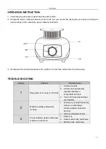
1.  Insert the plug into power socket that has earth contact. 
2.  Rotate the switch, clockwise direction from 0-180 min, you can set the drying time you need, machine will 

start working, at the meantime, power indicator illuminate. 


3.  Rotate switch knob anti-clockwise to On position, the machine will set it work continuously. 


TROUBLE SHOOTING 

Number 

Problem 

Possible cause 

Drying time is too long (> 180 min) 

1.  Clothes too thick. 
2.  Clothes not spin-dried by 

washing machine or 
screw-dried by hand. 

3.  Cover not close appropriately 

wind leaking. 

Machine suddenly stop when 
working 

1.  Wind-entry or outlet blocked by 

clothes or other things, 
machine startup protection 
process. 

2.  Having exceeded set time. 

P

ower indicator doesn’t illuminate, 

machine do not work. 

1.  Power cut. 
2.  Power socket fuse melt break. 
3.  Machine fuse melt break. 


OFF 

ON 

3 H 

1 H 

2 H 

Summary of Contents for CD01B

Page 1: ...Suszarka do ubrań Clothes Dryer CD01B QUICK DRYER PL EN ...

Page 2: ...nywane przez dzieci pozostawione bez nadzoru 11 Nie przechowuj w urządzeniu substancji wybuchowych oraz łatwopalnych takich jak aerozole dezodoranty oraz innego typu gazy sprężone 12 OSTRZEŻENIE To urządzenie przeznaczone jest wyłącznie do suszenia tkanin pranych w wodzie 13 To urządzenie nie jest przeznaczone do użytku przez osoby w tym dzieci o ograniczonych zdolnościach fizycznych sensorycznych...

Page 3: ...za Wilgoć usuwana jest w wyniku wydmuchiwania powietrza na zewnątrz komory przez otwory znajdujące się w górnej części suszarki DANE TECHNICZNE Rozmiar opakowania 710 x 240 x 265 mm Waga brutto urządzenia 5 5 kg Waga netto urządzenia 6 5 kg Rozmiar opakowania zbiorczego 725 x 495 x 290 mm Napięcie znamionowe 220 240V Częstotliwość znamionowa 50 60 Hz Moc znamionowa 1000 W Standardowy czas suszenia...

Page 4: ...tworach znajdujących się na uchwytach 4 składane uchwyty przystosowane są do montażu blokad w celu ustawienia właściwej pozycji Rura Φ 25 mm x 630 mm 4 szt Rura Φ 25 mm x 690 mm 9 szt Pokrowiec 1 szt Kółka 4 szt w tym 2 szt z blokadą Urządzenie bazowe 1 szt wciśnij do końca ...

Page 5: ...dą oraz jedno bez blokady 3 Umieść obydwie końcówki 2 rur o wymiarach Φ 19 mm x 680 mm w otworach znajdujących się na środku uchwytów dolnych 4 Umieść 4 rury Φ 25 mm x 690 mm w otworach znajdujących się na złożonej podstawie zacisk kółko uchwyt dolny wciśnij do góry uchwyt dolny rura Φ 19 mm Φ 19 mm x 680 mm Φ 25 mm x 690 mm wciśnij do końca ...

Page 6: ...owych mieściły się 4 rury zamontowane na dolnych uchwytach 6 Umieść 2 rury Φ 25 mm x 630 mm w bocznych otworach uchwytów środkowych 7 Umieść 6 rur Φ 12 mm x 670 mm w odpowiednich otworach uchwytów środkowych Φ 25 mm x 630 mm rura Φ 25 mm uchwyt środkowy wsuń wciśnij Φ 12mm x 670 mm ...

Page 7: ...mm x 690 mm w celu stabilizacji konstrukcji 10 Środkową część konstrukcji należy zamontować na czterech rurach dolnej części konstrukcji w sposób pokazany na rysunku Φ 25 mm x 630 mm Φ 25 mm x 630 mm Φ 25 mm x 690 mm górny uchwyt rura Φ 25 mm Φ 25 mm x 690 mm rura Φ 25 mm górny uchwyt wciśnij do końca wsuń umieść środkową część konstrukcji w 4 otworach dolnej części na środkową część nałóż górną c...

Page 8: ...konstrukcji Wylot powietrza powinien zostać umieszczony w otworze pokrowca Następnie złóż pokrowiec zgodnie z poniższym schematem 12 W celu zakończenia montażu zapnij zamek pokrowca DEMONTAŻ URZĄDZENIA W celu demontażu urządzenia wykonaj powyższe czynności montażu w odwrotnej kolejności ...

Page 9: ...żliwa przyczyna 1 Czas suszenia jest zbyt długi 180 min 1 Ubrania są zbyt grube 2 Odzież nie została wcześniej wywirowana 3 Pokrowiec nie został zamknięty ulatnia się powietrze 2 Maszyna nagle zatrzymuje się podczas pracy 1 Wlot lub wylot powietrza został zablokowany przez odzież lub inne rzeczy uruchomione zostało zabezpieczenie przed przegrzaniem 2 Przekroczony został ustawiony czas pracy 3 Wska...

Page 10: ... tego osobę ani też uszkodzone w wyniku nieprawidłowego użycia lub transportu Gwarancja nie obejmuje naturalnego zużycia się elementów ani elementów łatwo tłukących się jak szkło czy ceramika Niniejsza gwarancja nie ogranicza ustawowych praw konsumenta ani innych praw jakie konsument posiada zgodnie z obowiązującymi przepisami które dotyczą zakupu przedmiotów użytkowych W przypadku roszczenia gwar...

Page 11: ...iance 12 WARNING This appliance is intended only for drying textiles washed in water 13 This appliance is not intended for use by persons including children with reduced physical sensory or mental capabilities or lack of experience and knowledge unless they have been given supervision or instruction concerning use of the appliance by a person responsible for their safety 14 This appliance is for h...

Page 12: ...n size 725 x 495 x 290 mm Rated voltage 220 240V Rated frequency 50 60 Hz Rated power 1000W Standard clothes drying period 0 180 min KNOW YOUR CLOTHES DRYER PARTS AND COMPONENTS 2 pcs under racks 2 pcs middle racks 2 pcs top racks 8 pcs plastic positioning pin 6 pcs Φ 12 mm x 670 mm round tubes 2 pcs Φ 19 mm x 680 mm round tubes ...

Page 13: ...oles of the folding tubes and insert them in place All 4 pcs folding pipes are inserted into the positioning pins to set the position 4 pcs wheels 2 with brake 1 pc main machine 4 pcs Φ 25 mm x 630 mm round tubes 9 pcs Φ 25 mm x 690 mm round tubes 1 pc Cloth cover insert underneath ...

Page 14: ...nd a non brake 3 Insert the 2 pcs bottom frames into the middle side holes with 2 pcs round tubes are Φ 19 mm x 680 mm 4 Insert 4 pcs Φ 25 mm x 690 mm round tubes into the base frame holes clamp spring wheel under frame insert into the upside under frame Φ 19 mm round tube Φ 19 mm x 680 mm Φ 25 mm x 690 mm insert underneath ...

Page 15: ... angle holes at the bottom of the lower bracket 6 Insert 2 pcs Φ 25 mm x 630 mm round tubes into the base middle frame side holes 7 Insert 6 pcs Φ 12mm x 670 mm round tubes into the relative holes Φ 25 mm x 630 mm Φ 25 mm round tube middle frame insert clip into Φ 12mm x 670 mm ...

Page 16: ... 690 mm were inserted into the upper bracket hole for positioning 10 The middle frame shall be installed on the four straight pipes of the bottom frame at the same time and inserted as shown in the figure Φ 25 mm x 630 mm Φ 25 mm x 630 mm Φ 25 mm x 690 mm upper frame Φ 25 mm round tube Φ 25 mm x 690 mm Φ 25 mm round tube upper frame insert underneath insert middle frame should insert into 4 holes ...

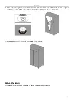
Page 17: ...let of the main machine is aligned with the inlet at the bottom of the cloth cover and then put the cover on as it has shown 12 Pull the zipper on the cloth cover to complete the installation DISASSEMBLING To disassemble this machine just follow the above installation steps contrarily ...

Page 18: ...ork continuously TROUBLE SHOOTING Number Problem Possible cause 1 Drying time is too long 180 min 1 Clothes too thick 2 Clothes not spin dried by washing machine or screw dried by hand 3 Cover not close appropriately wind leaking 2 Machine suddenly stop when working 1 Wind entry or outlet blocked by clothes or other things machine startup protection process 2 Having exceeded set time 3 Power indic...

Page 19: ...nly valid if the appliance has been used in accordance with the instructions and provided that it has not been modified repaired or interfered with by any unauthorised person or damaged by misuse or transportation The warranty does not apply to defects resulting from natural wear of components or nor breakables such as glass and ceramic items If you need a help please contact seller or directly YO...

Page 20: ...Producent Yoer Bernardyńska 2 64 000 Kościan Polska www yoer pl www yoer pl CD01B QUICK DRYER ...

Reviews: