


1.
Introduction
Galaxy G1200S is a broadband gateway, which converts protocols and data from
Fractional E1/T1 to Ethernet 10/100 BaseT interfaces. A pair of Galaxy G1200S can
thus make an Intranet bridge connection at Nx64Kbps through E1/T1 network. Galaxy
G1200S provides an E1/T1 interface, and support E1/T1 framed and unframed modes
with different line codes plus line build-out (LBO) capability.
G1200S is indeed an ideal symmetrical broadband solution for Intranet LAN-to-LAN
connection with Nx64Kbps bandwidth. This provides for the user with various Ethernet
LAN services (e.g. Video Conferencing, Routing, etc.) through Fractional E1/T1 network.
2. Features
z
Support Fractional E1/T1 Framed and Unframed modes
z
BNC connectors for E1 unbalanced 75 ohm
z
RJ-48 connector for E1 balanced 120 ohm and T1 balanced 100 ohm
z
Ethernet Auto-Detection for 10/100 BaseT and Half/Full duplex
z
Ethernet Auto MDIX function for auto Tx/Rx swap
z
6 LED indicators for status monitoring
z
Dip switches for configurations & settings
3. Packing Contents
Inside the package you should find:
(1)
One G1200S with dimension of 260x151x44 (mm)
(2)
One power cord
(3)
One Cat 5 Ethernet LAN cable
(4)
One E1/T1 RJ-48 to Y-connector cable
(5)
One user’s manual
Please check if the packing is damaged before unpacking or any component is missing.
4. Installation
1.
Select the Fractional E1/T1 interface configurations via SW1~SW7 dip switches.
2.
Connect E1/T1 line to the BNC or RJ-48 connectors on the back panel of
G1200S.
3.
Connect the Ethernet cable to the RJ-45 LAN connector of G1200S.
4.
Connect the power cord to the AC outlet, or Screw the -48V DC power.
5.
Turn on the power switch.
6.
The LED indicators of E1/T1 and LAN should be lit, and the LAN indicator will flash
to show the data activity of Ethernet. The LED indicator of LOS will be RED lit, when
E1/T1 is in Loss of Signal.
5. Front Panel LEDs
z
POWER
: G1200S power is ON.
z
E1
:
“ON” indicates that E1 is selected (SW1-1 is OFF)
z
T1
:
“ON” indicates that T1 is selected (SW1-1 is ON)
z
LOS
:
“ON” indicates Loss of Signal for selected E1/T1
z
10/100M
“ON” indicates Ethernet is in 100M connection
z
LAN
:
“ON & Flashing” indicates a normal LAN connection / data activity
6. DIP Switches
DIP Switches
OFF
ON
Functions
SW1-1
E1 T1 E1/T1
Selection
SW1-2
See Table A
See Table A
IMPEDANCE
SW1-3
See Table B
See Table B
FRAME MODE
SW1-4
See Table B
See Table B
FRAME MODE
SW1-5
See Table C
See Table C
LINE CODE
SW1-6
See Table D
See Table D
LBO
SW1-7
See Table D
See Table D
LBO
SW1-8
See Table D
See Table D
DSX-1
SW2-1
See Table D
See Table D
DSX-1
SW2-2
Reserved
Reserved
Reserved
SW2-3
Reserved
Reserved
Reserved
SW2-4
Reserved
Reserved
Reserved
SW2-5
Nx64
Nx56 (For T1 only) 64K/56K Channel
SW2-6
Full T1/E1
Fractional T1/E1
FRACTIONAL
SW2-7
All Zeros
All Ones
Stuff bits
SW2-8
Internal.
External.
E1/T1 Clock Mode
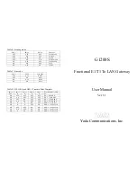
Table A. E1/T1 Impedance
SW1-1 SW1-2
Impedance
OFF ON
75
Ohms
OFF OFF
120
Ohms
ON OFF
100
Ohms
ON ON
100
Ohms


