


47
8.2.5
Remove the connection parts of cutting set in the right order.
. (PICTURE 10 NO 23/25/26)
8.2.6 Remove the saw carefully
8.2.7 Mount the saw by being sure that the rotation direction onto the axle is true.
8.2.8
Replace all removed parts in the same order.
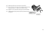
8.2.9 By holding the M10 Allen screw by 8mm Allen switch and the saw axle simultaneously by 17 switches tighten in
the direction of clockwise.
8.2.10
The saw selection should be made proper to EN 847-1 Standard
.
Summary of Contents for SC 550P
Page 4: ...4 BOYUTLAR DIMENSIONS РАЗМЕРЫ RESİM FIGURE РИСУНОК 1 ...
Page 5: ...5 KESME DİYAGRAMI CUTTING DIAGRAM ДИАГРАММА РЕЗКИ ...
Page 34: ...73 ELECTRIC PNEUMATIC DİAGRAM ...
Page 35: ...74 3P ELECTRICAL DIAGRAM SHEET 1 ...
Page 36: ...75 3P ELECTRICAL DIAGRAM SHEET 2 ...
Page 37: ...76 3P ELECTRICAL DIAGRAM SHEET 3 ...
Page 38: ...77 3P ELECTRICAL DIAGRAM SHEET 4 ...
Page 39: ...78 3P ELECTRICAL DIAGRAM SHEET 5 ...
Page 40: ...79 3P ELECTRICAL DIAGRAM SHEET 6 ...
Page 41: ...80 PNEUMATIC DIAGRAM ...