background image

69

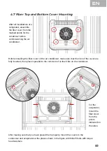
4.7 F ber Top and Bottom Cover Mount ng

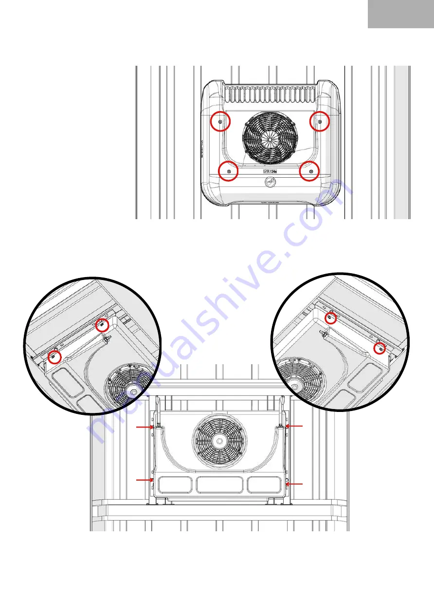
After all installations are
completed, assemble
the fiber cover from the
marked points for the
condenser before
commissioning the air
conditioner.

Before installing the fiber cover of the air conditioner, make sure that the tires of the cover are
fully inserted, then place it parallel to the vehicle roof so that it fits on the condenser.

After making sure that you have placed them properly, mount the covers to the
condenser and evaporator at the places shown in the figure with M6x25 bolts with torque
head washers.

For the
evaporator,
mount the
fiber cover
from the
points
indicated on
the sides.

EN

Summary of Contents for YS 50

Page 1: ...tion SSH MT 01 17 TR EN De i iklik yapma hakk sakl d r T rkiye de bas lm t r Y lkar Klima 2023 The right to make changes is reserved Printed in Turkey Y lkar Airconditioned 2023 EN Dijital kopyas i in...

Page 2: ...IN TAR H PUBLISH DATE REV ZYONU YAPAN K REVISING PERSON REV ZYON NEDEN REASON FOR REVISION SSH MT 01 17 TR EN De i iklik yapma hakk sakl d r T rkiye de bas lm t r Y lkar Klima 2023 The right to make c...

Page 3: ...4 2 nitenin Konumland r lmas ve Tavan Montaj 17 2 1 YS 50 Nedir 2 2 Nas l al r 2 3 YS 50 Teknik Veriler 4 5 1 1 Klima Hortumlar 21 4 6 Elektrik Ba lant lar 24 4 6 2 Kablo Ba lant s ve Devre emas 26 4...

Page 4: ...aland rma Modu 4 6 4 1 Is tma Modu 29 29 29 29 6 1 Kondanser Yedek Par alar 6 2 Evaporat r Yedek Par alar 6 3 Di er Yedek Par alar 34 38 36 4 7 Fiber st Ve Alt Kapak Montaj 31 SSH MT 01 17 TR EN De i...

Page 5: ...ty and Legal Regulations 2 Definition and Technical Information 3 Overview 3 2 General Description 4 1 General Assembly Diagram 4 5 Hoses and Fitting 4 5 1 Air Conditioner Hoses and Fitting Connection...

Page 6: ...Air Conditioner 6 Spare Parts 7 Usage and Maintenance Recommendations 6 1 Condenser Spare Parts 6 2 Evaporator Spare Parts 6 3 Other Spare Parts 71 72 73 67 67 67 67 72 76 74 69 SSH MT 01 17 TR EN De...

Page 7: ...n g venli kullan m na dair bilgiler i ermektedir Y lkar klima montaj n tam olarak yapman z i in l tfen bu montaj talimat n dikkatlice okuyunuz G venli ve temiz yerde muhafaza edilmesi tavsiye edilir S...

Page 8: ...m hangisi nce ger ekle irse garanti kapsam i indedir r n n garanti s reci i inde ar zalanmas durumunda tamirde ge en s re garanti s resine ilave edilir Bu s re r n n yetkili servise teslimi ile birlik...

Page 9: ...o umad ysa ayn durum fan zerindeki diren i inde ge erlidir Hatal par alar derhal de i tiriniz ve tespit edilen hatalar d zelttiriniz Bak m tamir i lemlerinde gerekli g venlik ekipmanlar n kullanmak zo...

Page 10: ...YS 50 frigorifik so utucu ara i erisindeki s y alarak frigorifik kasadaki r nlerin so utulmas n sa layan s makineleridir Ara tavan klimalar termodinamikte buhar s k t rmal so utma evrimi ile al r Bu e...

Page 11: ...porat r Fan Debisi 2000 m sa 1 Aksiyel Fan i in Kondanser Fan Debisi 2000 m sa 1 Aksiyel Fan i in Bas n alteri Al ak Bas n M r 0 5 1 5 bar 4 Yollu M r 2 15 25 bar D nite l leri nite l leri Uzunluk x G...

Page 12: ...NDENSER GRUBU YS 50 1 ADT 502 11 YS050 01 2 U CIFTLI RAY KULAK 70 CM KOMPLESI 1 SET 502 51 UC005 01 3 KLIMA TAKOZ BAGLANTI KOMPLESI 20 MM 1 SET 504 01 YKMON 01 4 KLIMA HORTUM BAGLANTI GROMETI 1 ADT 50...

Page 13: ...311 01 YS050 01 12V 311 01 YS050 21 24V 5 EVAPARATOR GRUBU YS 50 1 ADT 501 21 YS050 01 6 HORTUM CELIK TEL SPIRAL 12 MM 5 MT 108 02 HC00M 12 7 U CIFTLI RAY KULAK 70 CM KOMPLESI 1 SET 502 51 UC005 01 6...

Page 14: ...ald y ksek bas n l R134a so utucu gaz n evreye s vererek s v hale ge ti i klima sistemi eleman d r Evaporat r Evaporat r kondenserden gelen R134a so utucu ak kan n valf yard m ile buharla t ran ve bu...

Page 15: ...Klima sistemi i in 12V ve 24V opsiyonlar bulunmaktad r R le Kart Klima Hortumu Kompres r klima sisteminde R134a klima gaz n s k t r p bas nc n artt ran sistemin pompas d r Klima sisteminde SAE J 2064...

Page 16: ...ak Bas n Hatt TR 4 1 Genel Montaj emas 4 Y lkar YS 50 Montaj Yukar daki montaj emas nda iklimlendirme cihaz sisteminde hortumlar ile birbirine ba lanan bile enler zerinde R134a so utucu ak kan n n ak...

Page 17: ...men nce evaporat r ve kondenser fiber kapaklar kar n z 11 Montaj Ad m 1 ncelikle U ba lant profillerini arac n z n tavan na uygun l lerde kesiniz Montaj Ad m 2 Kesilen U profillerinin ray kulak par al...

Page 18: ...profilleri konumu a a da g sterilen l de ara i inde tavan zerinde i aretlenmeli ve matkap u lu trapez M5x25 vida ile tavana montaj sa lanmal d r Bu ba lant i in 16 adet ba lant vidas kullan lmaktad r...

Page 19: ...delik a lmas gerekmektedir 4 adet ba lant takozlar i in 1 adet hortum ge i i i in 4 3 2 D nitenin Konumland r lmas ve Tavan D Montaj Ara zerinde herhangi bir kesik yapmadan nce arac n ak s n kart n z...

Page 20: ...rkezi hat ile belirleyiniz Montaj Ad m 6 YS 50 i in teknik resimde detaylar verilen delik a lacak yerleri fiber kapak l lerini referans alarak ara zerinde i aretleyiniz aretlenen yerleri uygun alet ve...

Page 21: ...Ad m 9 klimlendirme cihaz n z n kondanser nitesini arac n tavan nda yal t m n sa lad n z ba lant takozlar na denk gelecek ekilde yerle tiriniz niteyi ara tavan na montajlamak i in takozlara uygun ekil...

Page 22: ...TR YS 50 DI N TES ST G R N S R Y N 16...

Page 23: ...leri 895 575 202 Montaj Ad m 10 Evaporat r nitesini araca daha nceden montaj yap lan U profillere matkap u lu trapez alt k e ba M5x25 vidalar ile uygun ekilde montajlay n z 4 4 2 nitenin Konumland r l...

Page 24: ...18 YS 50 N TES ALT G R N S R Y N TR...

Page 25: ...4 5 Hortum ve Rekorlar klimlendirme sistemi fabrika taraf ndan i inde 20 bar bas n la g nderilmektedir Ba lant noktalar ndaki mevcut tapalar kar l rken i inde Azot gaz bulunup bulunmad kontrol edilme...

Page 26: ...sm ndaki kademenin arkas ndan ekilde g sterildi i gibi s k lmal d r Su tahliye hortumlar su ak na engel olmayacak ekilde en az 2 a l k e im verilmelidir 20 TR 5 16 HORTUM VE REKOR BA LANTISI 13 32 HO...

Page 27: ...lant lar Y lkar iklimlendirme sisteminde mevcut bulunan SAE J 2064 type E standartlar na uygun hortum e itleri bu hortumlara ait minimum b k lme yar ap ve bu hortumlarla kullan lan rekorlar a a daki t...

Page 28: ...1 3 Kelep e ve Plastik Adapt rler 1 ncelikle hortumlar d z bir ekilde kesiniz 1 2 Rekorun ge ece i hortumun i k sm n ya lay n z 3 Rekorlar hortumlara d zg n bir ekilde oturtunuz 2 3 4 Pense yard m yl...

Page 29: ...Arac n hareketli elemanlar ndan ve s cak b lgelerinden uzak tutunuz hatt n ge ece i t m keskin kenar ve k elerden izole ederek montaj yap n z Hortumlar minimum b k lme yar ap na uygun ekilde b k n z...

Page 30: ...ar ile y zeye ge irerek montajlay n z 4 6 Elektrik Ba lant lar nite konumu ergonomik olarak s r c n n eri ilebilece i bir alanda d z bir y zey olarak se ilmelidir Montaj y zeyi l leri 90x45 mm olmal d...

Page 31: ...nu sigortan n bir taraf na ge iriniz Di er M8 kablo ucunu arac n ak s n n kutbuna yerle tiriniz M5 pullu somunlar takarak kofra setinin montaj n tamamlay n z Son olarak arac n arj dinamosundan al nan...

Page 32: ...4 6 2 Kablo Ba lant s ve Devre emas 26 D S cakl k Sens r ase GND 4 YOLLU M R ALTERNAT R KOMPRES R EVAPORAT R FAN S cakl k Sens r 12V BATARYA AL AK BASIN M R KONDENSER FAN KL MA ALINAN TR...

Page 33: ...ak U Pembe 0 50 mm 6 D ACC Turuncu 0 50 mm 7 Kumanda Besleme Sar 0 50 mm 8 A C 9 S cakl k Sens r 1 NU Kablo 0 50mm 10 Sens r Ortak Ba lant Ucu 2 NU Kablo 0 50mm 11 D S cakl k Sens r 3 NU Kablo 0 50mm...

Page 34: ...rleri sayesinde klimay devreye al p kartmaya yard mc olur 28 3 6 2 1 5 4 7 Set S cakl Is tma A k Klape Kapal D S cakl k So utma A k Fan Kademe S cakl k 7 6 5 2 3 4 1 Klape A k 18 32 SET 21 Set s cakl...

Page 35: ...latmak i in so utma butonuna bas n Ekranda i areti kt nda kliman z so utma modunda al r Is tma modunu ba latmak i in s tma butonuna bas n Ekranda i areti kt nda kliman z s tma modunda al r opsiyonel H...

Page 36: ...E 1 S cakl k Sens r A k Devre Olu ma Nedeni Kablo kesilmi veya soket km olabilir Sens r ar zalanm veya k r lm olabilir Cihaz n Tepkisi Hata olu tu unda sistem kapan r ve ekranda hata kodu g sterilir...

Page 37: ...akmadan nce kapa n lastiklerinin tam olarak ge ti inden emin olunuz ard ndan kondenserin zerine tam oturacak ekilde ara tavan na paralel yerle tiriniz D zg n yerle tirdi inize emin olduktan sonra kapa...

Page 38: ...YS 50 ST VE ALT N TES SON G R N S R Y N 32 S R Y N ST G R N ALT G R N TR...

Page 39: ...nmas Kompres r taraf ndan ba lanan vakum pompas ile sistem vakumlan r Bu i lem so utucu gaz verilmeden nce sistemin i inde kalan hava ve nem vakum pompas ile sistemden d ar ya at lmas n sa lamaktad r...

Page 40: ...6 MUSUR DISI KOMPLESI 2 15 25 BAR 4 YOLLU x1 ADT 331 04 MDPP4 01 7 SAC HRP HIZLI BAGLANTI 5 8 FLANS x1 ADT 101 11 QCP00 01 8 BORU 2101 DEPO KONDANSER ARA BAGLANTI QUICK x1 ADT 101 12 02101 01 9 SAC HR...

Page 41: ...NO 3 x1 ADT 104 05 1SN01 30 18 INYON 5 8X18 U HAV 5 8X18 U OR x1 ADT 108 07 11001 01 19 MUSUR DISI KOMPLESI 0 5 1 5 BAR ALCAK BASINC x1 ADT 331 04 MDAB1 01 20 REKOR 14 DUZ SU TAHLIYE x1 ADT 108 07 210...

Page 42: ...18 32 SET 21 KOMPRESOR SANDEN SD5S14 x1 ADT 504 03 TR 36 D J TAL KL MA KONTROL PANEL x1 ADT 105 01 KU010 01 KOFRA x1 ADT 503 92 KFSET 01 6 3 Di er Yedek Par alar...

Page 43: ...snas nda her zaman orijinal yedek par a kullan lmal d r YILKAR taraf ndan onaylanmam olan par alar nitenin g venli ini ve d zg n al mas n olumsuz etkileyebilir Bu t r durumlarda nite GARANT kapsam nda...

Page 44: ...unca kurumalar n engeller Kondanser bataryas n d zenli olarak kontrol ediniz ve gerekirse s k t r lm hava kullanarak ve al minyum kanatlara zarar vermeyecek ekilde temizleyiniz Is de i tiricilere yak...

Page 45: ......

Page 46: ...nd includes information on safe use of the device Please read this installation instruction carefully in order to fully install Y lkar air conditioner It is recommended to be stored in a safe and clea...

Page 47: ...irst from the date of installation of the product In case the product fails during the warranty period the time spent in repair is added to the warranty period This period starts with the delivery of...

Page 48: ...n if it will run on the unit and it has not cooled down completely Replace faulty parts immediately and have any detected faults corrected It is mandatory to use the necessary safety equipment in main...

Page 49: ...take the heat inside the vehicle and provide cooling of the products in the refrigerated case Vehicle roof air conditioners work with a vapor compression refrigeration cycle in thermodynamics There a...

Page 50: ...Rate 2000 m h for 1 Axial Fans Condenser Fan Flow Rate 2000 m h for 1 Axial Fans Pressure Switch Low Pressure Sensor 0 5 1 5 bar 4 Way Sensor 2 15 25 bar Outdoor Unit Dimensions Indoor Unit Dimensions...

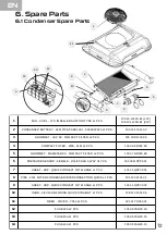
Page 51: ...0 1 PCS 502 11 YS050 01 2 U DOUBLE RAIL EAR 70 CM COMPLETE 1 SET 502 51 UC005 01 3 AIR CONDITIONING WEDGE CONNECTION ASSEMBLY 20 MM 1 SET 504 01 YKMON 01 4 AIR CONDITIONING HOSE CONNECTION GROMET 1 AD...

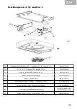
Page 52: ...5 7 6 EVAPARATOR UNIT YS 50 1 PCS 311 01 YS050 01 12V 311 01 YS050 21 24V 5 EVAPARATOR GROUP YS 50 1 PCS 501 21 YS050 01 6 HOSE STEEL WIRE SPIRAL 12 MM 5 MT 108 02 HC00M 12 7 U DOUBLE RAIL EAR 70 CM C...

Page 53: ...rom the compressor in the condenser air conditioning system becomes liquid by giving heat to the environment Evaporator Evaporator is an air conditioning system element that evaporates the R134a refri...

Page 54: ...24V options for the air conditioning system Relay Board Air Conditioner Hoses It is the pump of the system that compresses the R134a air conditioner gas in the compressor air conditioning system and...

Page 55: ...ER VALVE COMPRESSOR EVAPORATOR High Pressure Line Low Pressure Line In the above assembly diagram the flow direction of the R134a refrigerant and the low high pressure zones are shown on the component...

Page 56: ...remove the evaporator and condenser fiber covers Assembly Step 1 First of all cut the U connection profiles to the dimensions suitable for the roof of your vehicle Assembly Step 2 Assemble the U prof...

Page 57: ...as shown below and it should be mounted to the roof with a drill tipped trapezoidal M5x25 screw 16 connection screws are used for this connection VEHICLE ROOF FOR OUTDOOR UNIT CONNECTION U DOUBLE PROF...

Page 58: ...ssage 4 3 2 Outdoor Unit Positioning and Roof Mounting 4 3 1 YS 50 Outdoor Unit Dimensions 4 3 YS 50 Unit Mounting Before making any cuts on the vehicle remove the vehicle s battery Make sure that the...

Page 59: ...mounting criteria Assembly Step 6 For YS 50 mark the places to be drilled the details of which are given in the technical drawing on the vehicle by referring to the fiber cover dimensions Drill the m...

Page 60: ...e vehicle roof so that it coincides with the mounting wedges and the cut places In order to mount the condenser on the vehicle roof fasten it to the wedges with M10 nut in accordance with it Mount the...

Page 61: ...YS 50 OUTDOOR UNIT TOP VIEW 54 DRIVE DIRECTIO N EN...

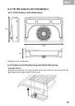
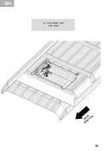
Page 62: ...Dimension Assembly Step 10 Assemble the evaporator unit to the U profiles previously mounted on the vehicle with drill tipped trapezoidal hexagon head M 5x25 screws 4 4 2 Indoor Unit Positioning and R...

Page 63: ...YS 50 INDOOR UNIT TOP VIEW DRIVE DIRECTIO N EN 56...

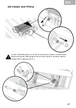
Page 64: ...nd Fitting The air conditioning system is sent by the factory with a pressure of 20 bar inside While removing the existing plugs at the connection points it should be checked whether there is Nitrogen...

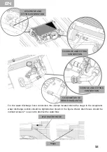
Page 65: ...e evaporator water discharge section should be tightened as shown in the figure Water drain hoses should be inclined at least 2 so as not to obstruct the water flow 5 16 HOSE AND FITTING CONNECTION 13...

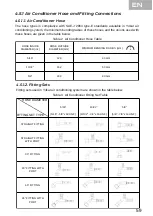
Page 66: ...hose types in compliance with SAE J 2064 type E standards available in Y lkar air conditioning system the minimum bending radius of these hoses and the unions used with these hoses are given in the t...

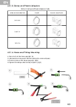
Page 67: ...05 4 5 1 3 Clamp and Plastic Adapters 1 First of all cut the hoses straight 1 2 Lubricate the inner part of the hose where the union will pass 3 Put the unions on the hoses properly 2 3 4 Tighten the...

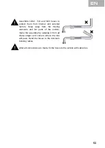
Page 68: ...ors Keep away from the moving elements and hot parts of the vehicle make the assembly by isolating it from all sharp edges and corners where the line will pass Bend the hoses to the minimum bending ra...

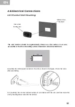
Page 69: ...y inserting these nails onto the surface 4 6 Electrical Connections The unit location should be ergonomically chosen as a flat surface in an area accessible to the driver Mounting surface dimensions s...

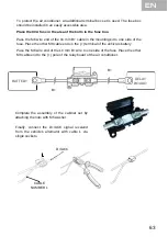
Page 70: ...o one side of the fuse Place the other M8 cable end on the terminal of the vehicle s battery Complete the assembly of the cabinet set by attaching the nuts with M5 washer Finally connect the D ACC sig...

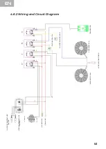
Page 71: ...KOMPRES R EVAPORAT R FAN S cakl k Sens r 12V BATARYA AL AK BASIN M R IN THE AIR CONDITIONER 4 6 2 Wiring and Circuit Diagram 64 OUTDOOR TEMPERATURE SENSOR INTERNAL TEMPERATURE SENSOR COMPRESSOR FOUR...

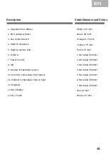
Page 72: ...Yellow 0 75 mm Pink 0 75 mm 6 D ACC 1 NU Cable 0 50mm 7 Power Control 2 NU Cable 0 50mm 8 A C 3 NU Cable 0 50mm 4 NU Cable 0 50mm 5 NU Cable 0 50mm 6 NU Cable 0 50mm 7 NU Cable 0 50mm 9 Internal Temp...

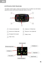
Page 73: ...robes in the unit 3 6 2 1 5 4 7 Set temparature Heating on Flap Closed Outside temparature Cooling on Fan speed Inside temparature 7 6 5 2 3 4 1 Flap Open 18 32 SET 21 Increase set temperature Decreas...

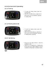
Page 74: ...ppears on the screen your air conditioner operates in cooling mode To start the heating mode press the heating button When the heating sign appears on the screen your air conditioner operates in heati...

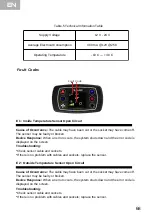
Page 75: ...re Sensor Open Circuit Cause of Occurrence The cable may have been cut or the socket may have come off The sensor may be faulty or broken Device Response When an error occurs the system shuts down and...

Page 76: ...er of the air conditioner make sure that the tires of the cover are fully inserted then place it parallel to the vehicle roof so that it fits on the condenser After making sure that you have placed th...

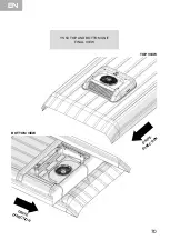
Page 77: ...70 YS 50 TOP AND BOTTOM UNIT FINAL VIEW DRIVE DIRECTIO N DRIVE DIRECTION TOP VIEW BOTTOM VIEW EN...

Page 78: ...The system is vacuumed by the vacuum pump connected by the compressor This process ensures that the air and moisture remaining in the system are discharged from the system with the vacuum pump before...

Page 79: ...89 5 GROMMET DIAMETER 89 COMPACT FILTER x2 PCS 103 07 GR000 89 6 PRESSURE SENSOR FEMALE 2 15 25 BAR 4 WAY X1 PCS 331 04 MDPP4 01 7 SHEET HRP QUICK CONNECT 5 8 FLANGE x1 PCS 101 11 QCP00 01 8 PIPE 210...

Page 80: ...lary x1 PCS 104 10 KD001 01 17 ORIFS SANHUA NO3 x1 PCS 104 05 1SN01 30 18 INION 5 8X18 x1 PCS 108 07 11001 01 19 PRESSURE SENSOR FEMALE 0 5 1 5 BAR X1 PCS 331 04 MDAB1 01 20 INION 14 FLAT WATER DISCHA...

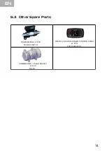
Page 81: ...18 32 SET 21 COMPRESSOR VALEO SD5H15 x1 PCS 504 03 74 DIGITAL AIR CONDITIONER CONTROL PANEL x1 PCS 105 01 KU010 01 TERMINAL BOX x1 PCS 503 92 KFSET 01 6 3 Other Spare Parts EN...

Page 82: ...parts should always be used during repairs Parts not approved by YILKAR may adversely affect the safety and proper operation of the unit In such cases the unit is out of WARRANTY For a fast and accura...

Page 83: ...f inactivity Check the condenser coil regularly and if necessary clean it using compressed air without damaging the aluminum fins When working close to heat exchangers be careful not to injure yoursel...

Page 84: ......

Page 85: ......

Page 86: ......

Page 87: ......

Page 88: ...Vehicle Heating Cooling and Ventilation Systems Phone 90 224 215 53 28 pbx Fax 90 224 215 99 24 Address K kbal kl Mah 580 Sok No 6 Osmangazi BURSA TURKEY www yilkarklima com...

Reviews: