
11
12
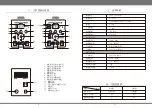
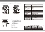
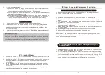
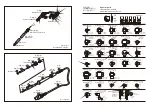
II. Schematic Diagram of the Host Panel
13
14
15
1. Hot air gun display status indicator
2. Soldering iron display status indicator
3. Up temperature adjustment button
4. Down temperature adjustment button
5. Gun switch
6. Air gun handle
7. Temperature display
8. Display status switch button
9. Airflow adjustment knob
10. Iron switch
11. Iron socket
12. Automatic / manual switch
13. Fuse
14. Power switch
15. Power line interface
1
2
3
4
5
6
7
8
9
10
11
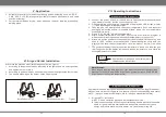
Standard Version
12
1
2
3
4
5
6
7
8
9
10
11
Upgrade Version
III. Specifications
Hot air gun part
Soldering iron part
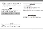
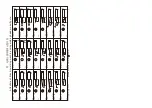
IV. Performance Comparison Table
Performance
Model
The standard version
Updated version
NO
NO
YES
YES
The LED switch
The LED switch
According to the form
Automatic blower gun manually
Soldering iron dormancy
100
~480
°C
°C
±
2
(
Static state
)
°C
200
~480
°C
°C
±
2
(Static state)
°C
<
2
Ω
<
2mV
≤
750W
0~40°C
-20~80°C
35%~45%
L148xW99xH140mm
±
5mm
2
.
5kg
Machine
240V/230V/220V/110V ±10% 50Hz/60Hz
Brushless fan gentle wind
120L/min (MAX)
26V±10% 50Hz/60Hz
Rated voltage
Whole device power
Overall size
Weight
Work environment
Storage temperature
Storage humidity
Temperature range
Temperature stability
Airflow type
Airflow
Work voltage
Temperature range
Temperature stability
Tip-to-ground impedance
Tip-to-ground voltage