background image

22

setup Overview 

The 303 RDH has full cable housing. utilizing full cable housing helps prevent 

corrosion from the elements and keeps the shifting smoother for a longer period of time. The 303RDH 
housing runs internally through the swing arm to protect it from being damaged by chain slap. 

Line Setup

setup 

CABLE ROuTING

Caution: 

The failure to properly route shifter housing can cause malfunction of the shift mechanism and unexpected 

shifting of gears

rear derailleur

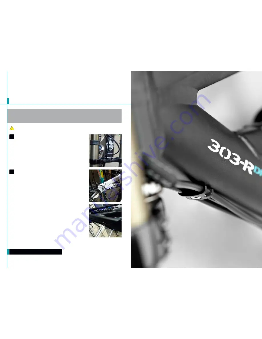
 Fit the housing from the rear shifter along the 

drive side of the head tube and down the cable stops.  There are 

three bolt-on cable stop groups on the down tube to which the housing 
and brake line can be attached, each with two positions to secure housing.  
Fit the rear housing line along the down tube into these stops, using the 
position closest to the drive side.  (Ensure the housing does not sag and 
rub on the lower crown of the fork.  This will cause excessive wear on the 
crown.)  Next, route the housing through the chainstay and loop onto the 
rear derailleur. 

rear brake

 The rear brake line loops across the head tube and into 

the bolt-on cable stops on the down tube.  use the position closest to 

the non-drive side on the cable guides for the rear brake line.

Next route the brake line above the bottom bracket shell and under the non 
drive chainstay.  use the single bolt-on cable guides on the bottom of the 
chainstay to secure the line.  Ensure the line is finished on the inside of the 
seatstay when attached to the caliper body.  This will prevent the brake line 
from being compromised if the bike or rider falls. 

1

2

Summary of Contents for 303R DH 2013

Page 1: ...YETICYCLES 600CORPORATECIRCLE UNITD GOLDEN CO80401 888 576 9384 USA 2010 303R DH OWNER S MANUAL ...

Page 2: ...res 8 Geometry 10 Maintenance Schedule 12 Rail System Lubrication 14 Eccentric Adjustment 16 Shock Setup 18 Shock Setup quick start guide 20 Cable Line Setup 22 Assembly Overview 24 Exploded Views 30 Part List 32 Warranty 34 Contact Information 35 ...

Page 3: ...cipate every situation or condition that may occur during the assembly setup and maintenance of your bicycle Warning Make sure you review and understand the warnings instructions and content of this manual and accompanying manuals for your bicycle Warning Technological advances have made bicycles and bicycle components more complex and the pace of innovation is increasing It is impossible for this...

Page 4: ... RDH chainstay protector is a 2 stage molded plastic an rubber piece that is attached to the frame via socket cap head bolts 4 Through axle 12 through axel spaced at 150mm Allows for a stiff and strong rear end 5 Shock 9 5 eye to eye 3 0 stroke 6 Linear Rail System The linear block contains four rows of ball bearings that circulate along the rail allowing the guide to move freely The linear rail h...

Page 5: ...ements are in inches Geometry 303 RDH s m l a 16 5 16 5 17 0 b 22 5 23 5 24 5 c 64 65 64 65 64 65 d 65 66 65 66 65 66 e 17 25 17 25 17 25 f 44 7 44 5 45 7 45 5 46 7 46 5 g 13 5 14 3 13 8 14 3 13 8 14 3 h 29 5 30 0 29 5 30 0 29 5 30 0 i 4 50 4 50 4 50 ...

Page 6: ...le Torque We have attached a brief list of torque specifications for bolts and components that may need to be tightened while performing basic maintenance This is just guide For specific torque specifications please contact the component manufacturer directly Torque Specs Swingarm Pivot Pins 40 50 Stabilizer Pinch Bolts 40 50 Titanium Pivot Bolts 125 150 Pivot Pins 125 150 Through Axle Bolts 125 1...

Page 7: ...arings are made from martensitic stainless steel which is equal to a 440 stainless End scrapers end seals inner seals and side seals prevent contaminants from entering the system There is also a custom grease port on the end of each block Grease should be applied with the supplied applicator after the days ride and or bike wash After grease application the suspension needs to be cycled 6 10 times ...

Page 8: ...ry of the bike via the eccentric mount The geometry can be adjusted from a 64 degree head angle 14 inch bottom bracket height through a 66 degree head angle 15 inch bottom bracket height 1 Eccentric adjustment Place a 5mm allen key into each eccentric insert as shown Rotate the eccentric to the desired position The eccentric adjustment has a range of 64 13 85 65 14 35 2 Eccentric adjustment Once t...

Page 9: ...ing Counter clockwise rotation Bottom out resistance The bottom out adjuster has 4 turns of adjustment This adjustment controls the bottoming resistance of the shock meaning it controls the compression on the final part of the shocks stroke The adjuster can be turned with a 3mm allen key inserted into one of the holes around the perimeter of the dial More Resistance clockwise rotation Less Resista...

Page 10: ...n 6 Clicks High Speed Compression 1 Turn Boost Valve 150 psi Sag Settings Sag 25 30 35 Eye To Eye inches 8 750 8 600 7 95 All Clicks are clockwise rotation from all the way out or a full counter clockwise position Spring weights 303 RDH Spring chart in lbs 350 400 450 Min rider weight lbs 145 165 185 Max rider weight lbs 165 185 215 ...

Page 11: ... two positions to secure housing Fit the rear housing line along the down tube into these stops using the position closest to the drive side Ensure the housing does not sag and rub on the lower crown of the fork This will cause excessive wear on the crown Next route the housing through the chainstay and loop onto the rear derailleur rear brake The rear brake line loops across the head tube and int...

Page 12: ...re your tools are in good condition A worn allen key can round the hex on a bolt not allowing for proper torque Torque settings are listed throughout the instructions It is also import to prep all bolt threads The instructions denote whether to use a blue Loctite compound or grease The linkage tool is necessary to properly disassemble and reassemble the linkage Using a hammer to tap out the pin ca...

Page 13: ...ve and non drive side specific 6 main Assembly Place the car mount assembly onto the THK car and tighten with four M4x 7x8mm bolts Prep the bolt threads with locktite Torque 20in lbs main Assembly Attach the rail sub assembly to the frame with three 4x 7x16mm socket head bolts Prep the bolt threads with locktite Tighten the bolts using a 3mm allen key Torque 40in lbs main Assembly Rotate each of t...

Page 14: ...a M6x1x12 Ti male bolt Use the guide pin tool to align the shock in the frame while inserting the female bolt Main assembly Ensure the female bolt enters the frame through the drive side and that each Ti bolt has the appropriate washer Apply locktite to the male bolt and tighten using two 5mm allen keys Torque 100 125 in lbs CHAINSTAY PROTECTOR The 303 RDH has a bolt on chainstay protector Install...

Page 15: ...2 7mm x 18mm 2 17 Pivot Pin Cap 12 7mm x 12mm 4 18 Bearing 3903 2rs Double Row 2 19 Bearing 37802 2rs Max 4 20 Stud Ti Female M6 X 8 X 57 5 mm 1 21 Bolt Ti Female M6 X 31 MM 1 22 Bolt Ti Male 6x1x12mm 3 23 Washer 8 5 X 12 5 X 0 5 MM 2 24 Washer 6 5 X 12 5 X 0 5 MM 2 25 Bolt Cap Skt HD M6x1x18 mm 3 26 Barrel Insert M6 1 27 Bolt Cap Skt HD M4x 7x16 mm 3 28 Bolt Flat HD M4x 7x 8 mm 4 29 Bolt Flat HD ...

Page 16: ...300030069 WASHER SS 8 5MM ID 12 5MM OD 2 300030110 BOLT TI MALE M6X1 12MM 3 300030134 BOLT FLAT HEAD M4X7X8 4 300030135 BOLT FLAT HEAD M4X7X12 8 300030186 BOLT TI FEMALE 8 0X31 0MM 1 300030189 PIVOT PIN BOLT M10 X 1 X 22 1 300030191 STUD TI FEMALE 8X57 5MM 1 300030205 PIVOT PIN M10 17MMX67 5MM 1 300030206 PIVOT PIN MALE 12 7MMX18MM 2 300030207 PIVOT PIN CAP 12 7MMX12MM 4 300040378 303 RDH ECCENTRI...

Page 17: ... frameset must be presented to an authorized Yeti dealer together with proof of purchase ū ū The above warranties have been in effect since January 2000 All Yeti frames sold prior to that date had a limited 1 one year warranty on the frameset ū ū No Fault Replacement Policy ū ū Yeti Cycles will make replacement parts available at a minimum charge to the original owner in the event of a crash or an...

Reviews: