background image

Page 5 of 47 


25.12.2018    

                DIS-14-ek 

                      Rev Nr: 2 


1.0


About this handbook 

 
This handbook describes the installation and operation of Yenen autogas (LPG) dispensers. For the 
installation and operation of the employed electronic systems refer to the operation guides of the relevant 
systems. 
 
For any questions relevant to the installation and operation of the dispenser that are not covered in this 
handbook, please contact Yenen through [email protected] or call +90 216 487 5924. 


Summary of Contents for Autogas LPG Dispensers

Page 1: ...ensers Installation and Operation Handbook Document Name Autogas Dispensers Installation and Operation Handbook Document Code DIS 14 ek Number of Page 47 Issue Date 28 06 13 Revision No 2 Revision Dat...

Page 2: ...ch may cause serious personal injury damage to property if not observed cautiously This handbook provides instructions and rules Remarks and warnings inform the operator about the dangers relevant to...

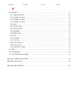
Page 3: ...ion test 13 2 6 1 Preset 14 2 6 2 Non volatile memory test 14 2 6 3 Emergency shut down system 14 2 6 4 Flow interruption 14 3 0 Operation 15 3 1 Before commissioning the dispenser 15 3 2 Programming...

Page 4: ...6 High Flow Valve 26 6 4 7 Low Flow Valve 26 6 4 8 Hide Pulses 27 6 4 9 Display Points 27 6 4 10 ATC 27 6 4 11 Calibration 28 6 4 12 Low Flow 28 6 4 13 Low Flow Time 29 6 4 14 No Low Time 29 6 4 15 Au...

Page 5: ...autogas LPG dispensers For the installation and operation of the employed electronic systems refer to the operation guides of the relevant systems For any questions relevant to the installation and op...

Page 6: ...sconnect the power supply before commencing maintenance There may more than one latch to disconnect Use a multimeter to make sure that all circuits in the dispenser are closed Failure to take this pre...

Page 7: ...n doubt inform the fire department thereof In case of gas flare 1 Shut the leakage if its location is safe to reach 2 If it is a flare that cannot be controlled safely contact fire department 3 If it...

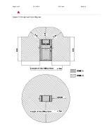
Page 8: ...gulations first Figure 2 1 shows dangerous zones in accordance with European CEN regulations Zone 0 Constant or long term presence of an inflammable and explosive atmosphere 1000 hours year Where In t...

Page 9: ...Page 9 of 47 25 12 2018 DIS 14 ek Rev Nr 2 Figure 2 1 Dangerous Zone Diagram...

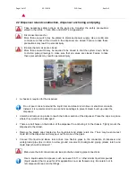
Page 10: ...cal conduits Instead it is recommended to use sand or sandbags to prevent steam build up under the dispenser Unlatch and remove cap locks to reach the bottom section of the dispenser Place the caps in...

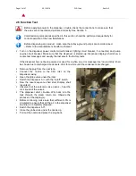
Page 11: ...to each hose Only a couple cubic centimeters of LPG escape during removal Check the electrical continuity on the hose nozzle connection There should be no continuity between the dispenser outlet and...

Page 12: ...For full service and stand alone operation make electrical installation in accordance with the electrical connection scheme in the Appendix A A display lighting circuit that is connected to the power...

Page 13: ...sale in the factory tests If the dispenser has not been powered or used for a while an error message like no electricity shall be shown due to discharged condensers Wait for a while until the condens...

Page 14: ...Switch the dispenser off The display shall show no electricity message and the last process for 20 minutes The data shall be stored in EPROM and displayed again when the power is restored The last pr...

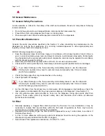
Page 15: ...efault from factory this compound is preset to 30 butane and 70 propane For accurate measurements it important to set ATC in accordance with the LPG compound Neglect this responsibility may result in...

Page 16: ...ge on the hose assembly immediately cease to use the dispenser Continuing to operate it may result in personal injury and property loss Close all valves and fix hose assembly Check for sharp edges tha...

Page 17: ...ions at least once a year or if there are any changes in the LPG inventory Some precise measurement parts are sealed in order to restrict their repair and modification Only authorized and certified pe...

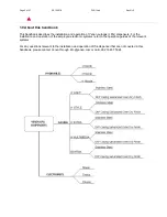
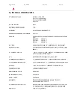
Page 18: ...ce has the feature of temperature compensation for 22 different LPG and FUEL types Two nozzles are active at the same time Two MCU s are used for each nozzle sake of reliable operation Main LCD screen...

Page 19: ...CONTACTS CLOSED TYPE RELAY HYDRAULIC OUTPUT 1 INPUT 2 OUTPUT DRY CONTACTS COMMON VOLTAGE INPUT CLOSED TYPE RELAY ATC 22 PRODUCTS DISABLED CAN BE LEFT TEMPERATURE PROBES 0 1 DEGREE SENSITIVITY SEMICON...

Page 20: ...ICE is independent The UNIT PRICE can be changed by the user without use of service terminal if the computer is not in AUTO CASH REGISTER mode The connection plug of service terminal is protected by a...

Page 21: ...creen P3 is used for entering new value Enter key is used to save the entered value and C key is used to quit 1 LANGUAGE SELECTION 2 P1 MONEY P1 LITERS 3 P2 MONEY P2 LITERS 4 P3 MONEY P3 L TRE 5 PULSE...

Page 22: ...0 TURKISH 001 ENGLISH P3 PRESS SCREEN ENTER THE VALUE PRESS THE ENTER 6 4 2 P1 MONEY P1 VOLUME SCREEN P3 PRESS SCREEN ENTER THE VALUE PRESS THE ENTER SCREEN SCREEN P1 PRESS LANGUAGE OLD XXX LANGUAGE N...

Page 23: ...NTER SCREEN ENTER THE VALUE PRESS THE ENTER SCREEN 6 4 3 P2 MONEY P2 VOLUME SCREEN P3 PRESS SCREEN ENTER THE VALUE PRESS THE ENTER SCREEN SCREEN P1 PRESS LITER MONEY BUTTON PRESS P1 VOLUME OLD XXXXXX...

Page 24: ...UE PRESS THE ENTER SCREEN 6 4 4 P3 MONEY P3 VOLUME SCREEN P3 PRESS SCREEN ENTER THE VALUE PRESS THE ENTER SCREEN SCREEN P1 PRESS LITER MONEY BUTTON PRESS SCREEN P2 VOLUME OLD XXXXXX P2 VOLUME NEW XXXX...

Page 25: ...PULSE SCREEN 1 TOUR 1 L TRE METERS 2X50 CHANNEL PULSER FOR XXXX 500 2 TOUR 1 L TRE METERS 2X50 CHANNEL PULSER FOR XXXX 1000 P3 PRESS SCREEN P3 PRESS SCREEN ENTER THE VALUE PRESS THE ENTER SCREEN P3 V...

Page 26: ...HIGH FLOW VALVE SCREEN P3 PRESS SCREEN ENTER THE VALUE PRESS THE ENTER SCREEN 6 4 7 LOW FLOW VALVE SCREEN P3 PRESS SCREEN ENTER THE VALUE PRESS THE ENTER SCREEN FAST UP OLD XXX FAST UP NEW XXX REGISTE...

Page 27: ...PRESS SCREEN ENTER THE VALUE PRESS THE ENTER SCREEN 6 4 9 DISPLAY POINTS SCREEN 223 STANDARD VALUE P3 PRESS SCREEN ENTER THE VALUE PRESS THE ENTER SCREEN 6 4 10 ATC SCREEN HIDE PULSES OLD XXX HIDE PUL...

Page 28: ...NT DENSITY P3 PRESS SCREEN ENTER THE VALUE PRESS THE ENTER SCREEN 6 4 11 CALIBRATION SCREEN 100000 STANDARD VALUE P3 PRESS SCREEN ENTER THE VALUE PRESS THE ENTER SCREEN 6 4 12 LOW FLOW SCREEN ATC OLD...

Page 29: ...PRESS THE ENTER SCREEN 6 4 13 LOW FLOW TIME SCREEN P3 PRESS SCREEN ENTER THE VALUE PRESS THE ENTER SCREEN 6 4 14 NO FLOW TIME SCREEN P3 PRESS SCREEN LOW FLOW NEW XXX REGISTERED LOW FLOW TIME OLD XXX...

Page 30: ...R SCREEN 6 4 15 AUTOMATION ADDRESS SCREEN 99XX AUTOMATION OFF 00XX AUTOMATION ON XX PUMP ADDRESS P3 PRESS SCREEN ENTER THE VALUE PRESS THE ENTER SCREEN RETURN BACK TO THE SCREEN SCREEN REGISTERED AUTO...

Page 31: ...n hook the nozzle or turn the nozzle switch the delivery stars LCD SCREEN DISPLAY 6 5 2 MANUAL TRANSACTION Hook the nozzle or turn switch and delivery starts In preset or manual delivery mode transact...

Page 32: ...ESS C OR WAIT 10 SECONDS TO QUIT 6 5 5 READING LAST TRANSACTION WITHOUT ATC CORRECTION PRESS 3 THEN PRESS ENTER SCREEN PRESS C OR WAIT 10 SECONDS TO QUIT 6 5 6 READING FLOW RATE MIN PRESS 0 WHILE DEL...

Page 33: ...EEDED IN PREST TRANSACTION VALVE LEAK EE 05 MECHANICAL TOTALIZER NOT CONNECTED EE 06 MECHANICAL TOTALIZER SHORT CIRCUITED EE 07 UNIT PRICE ZERO OR NOT SET EE 08 COMMUNICATION ERROR WHILE DEL VERY EE 0...

Page 34: ...LPG 02 0550 LPG 03 0555 LPG 04 0560 LPG 05 0565 LPG 06 0570 LPG 07 GASOLINE 08 EURO DIESEL 09 DIESEL 10 JET A1 LIGHTING KEROSENE 11 AVIATION GASOLINE 12 HIGH SULPHUR FUEL OIL 13 LOW SULPHUR FUEL OIL 1...

Page 35: ...Page 35 of 47 28 06 13 DIS 14 ek Rev Nr 1 Appendix A Cable Connection Diagram...

Page 36: ...TOR VOLTAGE IN E MECH TOTALIZER NOZZLE SWITCH GND CRLP PULSER PULSER CH B PULSER CH A KEYBOARD DISPLAY PULSER 1 2 3 7 8 9 6 4 5 1 Amper 220 V Relay 18 0 5 Ampers 19 20 21 EMERGENCY STOP 22 24 16 17 23...

Page 37: ...KI HIZLI VALF IKI I KEYBOARD DISPLAY YAVA VALF IKI I VALF VOLTAJ G R VALF VOLTAJ G R TOPRAK SERVICE 1 2 3 7 8 9 6 4 5 1 Amper 220 V Relay 18 0 5 Ampers 19 20 21 EMERGENCY STOP 22 24 16 17 23 7 8 9 6 4...

Page 38: ...should be replaced if not generating pressure f No signal from the relay f Check if a signal is received from the relay f Make sure that signal is received from relay g On off switch is broken g Check...

Page 39: ...lter may be clogged a Check the filter a Change the filter b Solenoids may be clogged or solenoid core may leak b Check the solenoids b Clean solenoid replace the core replace solenoid if necessary c...

Page 40: ...place solenonids Nothing on display a Display temperature may be more than 40o display is erased in this case a Check the display temperature a Problem shall be fixed when display temperature is norma...

Page 41: ...gas leakage a Check for leakages on all systems a Press gas alarm reset key for 3 seconds b Gas detector may be broken b Check the gas detector b Replace the gas detector Thermic relay on the panel bl...

Page 42: ...essure may be drooped a Check the pump pressure a Replace the pump if broken b Electrical interruption b Check the voltage b Restore electrical connection c Pressure sensor may be broken c Check the p...

Page 43: ...team and other dangerous conditions Disconnect and lock power supply before opening the dispenser for maintenance Make sure that valves under the dispenser are closed BEFORE commencing maintenance Be...

Page 44: ...the dispensers Do not left the dispenser caps open after completing maintenance Do not allow smoking igniting or fire devices within the perimeter of the work site Do not work outside of the barricade...

Page 45: ...45 Notes...

Page 46: ...Ak emsettin Mahallesi Tavuk uyolu Sokak No 23 Sultanbeyli 34925 Istanbul TURKIYE T 90 216 487 5924 F 90 216 487 5986 E info yenen com www yenen com...

Reviews: