background image


Yeastar  S100  Installation  Guide 


  12/15 

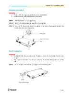
Desktop Installation 

WARNING 


Please set 5~10cm gaps around the device for air circulation. 


Please avoid any heavy thing placed on the device. 


STEP 1   

Place the IP PBX on a steady platform. 

STEP 2   

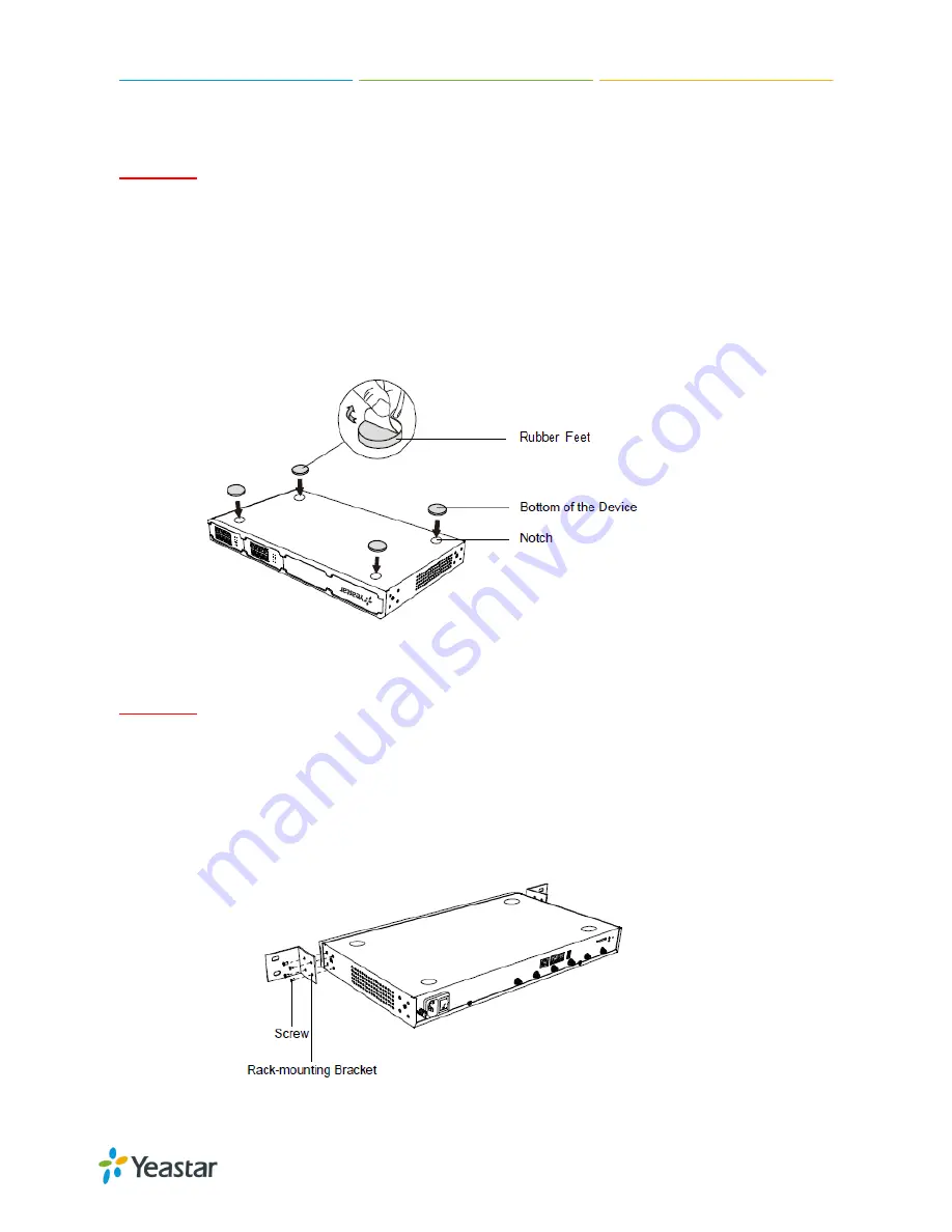
Remove the adhesive backing paper from the rubber feet. 

STEP  3   

Turn  over  the  device  and  attach  the  supplied  rubber  feet  to  the  recessed  areas  on  the 

bottom at each corner of the device. 


Rack Installation 

WARNING 


Be careful not to drop any components. Dropping components may damage them or cause 
an injury. 


Only  use  the  19-inch  rack  mounting  kits  (attached  bracket  and  fittings)  included  with  the 
PBX. 


STEP 1   

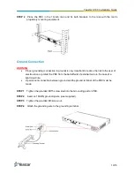
Fix the brackets to the left and right sides of the PBX with 4 screws. 


Summary of Contents for S100

Page 1: ...Yeastar S100 VoIP PBX Installation Guide Version 1 0 Jun 2016...

Page 2: ...eastar S100 Overview 5 LED Indicators and Ports 6 Installation 8 Safety Disclaimers and Installation Warnings 8 Telephony Module Installation 8 DSP Module Installation 11 Desktop Installation 12 Rack...

Page 3: ...Guide for instructions on how to perform configurations on the system Related Documents This Installation Guide only explains the installation of Yeastar S100 IPPBX For more functionality and advance...

Page 4: ...tact your provider Package Contents 1 S100 PBX 1 Ethernet Cable 1 Power Cord 2 Rack Mounting Kits 1 Grounding Stud Nut 4 Rubber Feet 1 Warranty card 1 Quick Start Guide Expansion Board Yeastar S100 su...

Page 5: ...EX30 EX30 board supports 1 E1 T1 port D30 Module D30 is a DSP module used to expand the capacity of PBX With per D30 module added the extensions increase 100 and concurrent calls increase 30 in additi...

Page 6: ...nection Off No LAN port connection Port Status FXS Green light Static The port is idle Blinking There is an ongoing call on the port GSM CDMA 3G Red light Static the trunk is idle Blinking slowly ther...

Page 7: ...responding ports at the front panel E1 T1 Port Connect the E1 T1 line ANT Rotate the antenna into the Antenna Socket USB Slot Connect a USB drive or mobile hard disk drive SD Slot Insert a SD card Eth...

Page 8: ...ation Make sure that the supply voltage matches the specifications indicated on the back panel of the device To avoid the electric accident do not open or remove the cover of IP PBX when it is working...

Page 9: ...Yeastar S100 Installation Guide 9 15 STEP 2 Push out the empty board from the inside of the device STEP 3 Push in the Expansion Board EX08 or EX30 STEP 4 Lock the screws to fix the Expansion Board...

Page 10: ...nsert the Telephony Modules on the EX08 Board Skip this step for EX30 Board STEP 6 Insert a SIM card on the GSM CDMA 3G module following the instructions Skip this step if no GSM CDMA 3G module instal...

Page 11: ...o the Antenna Socket Skip this step if no GSM CDMA 3G module installed DSP Module Installation STEP 1 Open the device upper cover and insert the DSP module D30 into the D Slot from a tilt angle and th...

Page 12: ...acking paper from the rubber feet STEP 3 Turn over the device and attach the supplied rubber feet to the recessed areas on the bottom at each corner of the device Rack Installation WARNING Be careful...

Page 13: ...duce the risk to the user of electrocution or protect the PBX from the bad effects of external noise in the case of a lightning strike A permanent connection between ground and the ground terminal of...

Page 14: ...1 cable to the FXO port Connect the other end of the cable to a PSTN line BRI Connect the cable provided by the ISDN BRI provider to the BRI port Connect the other end of the cable to the ISDN provide...

Page 15: ...assword password STEP 1 Connect your PC to the same network as Yeastar S100 STEP 2 Start the browser on PC In the address bar enter the IP address click Enter key and then you can see the web GUI logi...

Reviews: