14
O R I G I N A L I N S T R U C T I O N S
GB
D
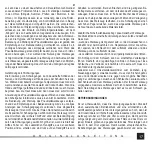
out recommended air supply system, frequency of tool inspection
should be increased.
Removal of failures
Immediately stop to use the tool after detection of any failures. Op-
eration of inoperable tool may cause injuries. All repairs or replace-
ments of tool components must be performed by qualifi ed staff in
authorised repair shop.
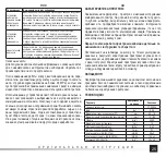
Failure
Possible solution
Tool’s
rotational
speed is too
low or it does
not start
Insert small quantity of WD-40 though air inlet slot. Start the tool
for few seconds. Blades could have stuck to rotor. Start the tool for
approx. 30 seconds. Lubricate the tool with small quantity of oil. Note!
Excess of oil may cause lowering of tools’ power. In this case clean
the drive.
Tolls starts
and then
slows down.
Compressor does not provide proper air infl ow. Tool is started using
the air accumulated in compressor’s tank. Along with the process of
emptying the tank, the compressor is not able to supplement the air.
Connect the tool to more effi cient compressor.
Insuffi cient
power
Make sure that hose’s internal diameter is at least equal to diameter
specifi ed in table in point 3. Check the settings of pressure, whether it
is set to maximum value. Make sure, that the tool is properly cleaned
and lubricated. If no eff ects are observed, have the tool repaired in
repair shop.
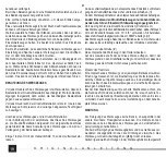
Spare parts
To obtain information on spare parts for pneumatic tools please con-
tact the manufacturer or his representative.
After the end of work, housing, ventilation slots, switches, additional
handle and cover should be cleaned, e.g. with an air jet (with a pres-
sure of no more than 0.3 MPa), brush or dry cloth without the use
of chemicals or cleaning fl uids. Tools and tool chucks to be cleaned
using dry and clean cloth.
Used tools are recycled materials- it is forbidden to throw them to
communal waste containers since they contain substances that
are dangerous to human health and environment! You are kindly
requested to help in economical management of natural resources
and protection of natural environment by delivering the used equip-
ment to point of storage of used equipment. To limit quantity of waste
it is necessary to re-use it, recycle or recover in other form.
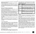
MERKMALE DES WERKZEUGES
Druckluft- Hammer ist ein Werkzeug, das mit der Druckluft betrie-
ben wird. Mittels Stemmeisen, Meißel, und Dorne, die in dem Halter
befestigt werden, ist das Stemmen und Durchlöchern der Metall-
werkstücke möglich. Die Werkzeuge sind für den Funktionsbetrieb
innerhalb von Räumen geeignet und dürfen keiner Feuchtigkeit und
atmosphärischen Niederschlägen ausgesetzt werden. Eine ein-
wandfreie und zuverlässige Funktion des Werkzeuges hängt von
der sachgemäßen Betriebsart, deshalb:
Vor Arbeitsbeginn soll die Betriebsanweisung sorgfältig durch-
gelesen und aufbewahrt werden.
Der Lieferant haftet nicht für Schaden und Verletzungen, die infolge
der nicht bestimmungsgemäßen Verwendung, Nichteinhaltung der
Sicherheitsvorschriften und der vorliegenden Betriebsanweisung ent-
standen sind. Die nicht bestimmungsgemäße Verwendung des Werk-
zeuges hat auch die Aufhebung der Garantieleistungen zur Folge.
ZUBEHÖR
Hammer ist mit einem Nippel zum Anschluss an die Druckluftinstal-
lation zusätzliche Stemmeisen, Dorne und Feder für den einwand-
freien und sicheren Einsatz des Werkzeuges ausgestattet.
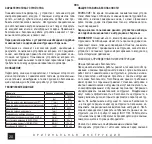
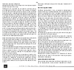
TECHNISCHE DATEN
Parametr
Maßeinheit
Größe
Katalognummer
YT-09904
Gewicht
[kg]
0,95
Durchmesser des Luftanschlusses (PT)
[” / mm]
6,3 / 1/4
Schlauchdurchmesser des Luftanschlusses
(Innendurchmesser)
[” / mm]
10 / 3/8
Schlagfrequenz
[min
-1
]
4500
Durchmesser der Werkzeughalterung
[mm]
10
Max. Betriebsdruck
[MPa]
0,63
Erforderlicher Luftdurchfl uss (bei 0,63 MPa)
[l/min]
113
Schalldruck (EN ISO 3744)
[dB(A)]
95 ± 3
Schallleistung (EN ISO 3744)
[dB(A)]
106 ± 3
Schwingungen (ISO 28927-9)
[m/s
2
]
20 ± 4,5


