31
EN
SAFETY INSTRUCTIONS
• If the carbon brushes need to
be replaced, have this done by a
qualified repair person (always
replace the two carbon brushes at
the same time).
ASSEMBLY
Starting to use the lawnmower
Power connection
Do not switch on the unit until it has
been completely assembled. Before
switching on the tool, always check the
connection cable for signs of damage;
only an undamaged connection cable
may be used. Damaged connection
cables are highly dangerous!
The electrical data of the electrical
supply must be the same as that
indicated in the rating plate of this
tool. Please do not use the tool if the
electrical data is different.
• Insert the main plug of the
unit connection cable into the
combined switch/plug
• Secure with the cable grip. The
loop of the mains cable must be
long enough for the cable grip to
slide from one side to the other.
Switching ON and OFF
• Switching on: press the button on
the combined switch/plug. Hold
down the ON button and pull the
switch bar towards the handle and
hold in position
• Switching off: release the switch bar
WARNING:
When the motor has been
switched off, the cutter continues to
run for several seconds. Therefore,
do not touch the underside of the
mower until the cutter has come to a
standstill.
Preparation
• While mowing, always wear
suitable footwear and long
trousers.
• Do not operate the appliance when
barefoot or wearing open sandals.
• Thoroughly inspect the area where
the appliance is to be used and
remove all stones, sticks, wires,
bones, and other foreign objects.
• Before use, always inspect visually
to see if the blades, blade bolts,
and cutter assembly are not worn
or damaged. Replace worn or
damaged blades and bolts in sets
to preserve balance.
• On multi-bladed appliances, take
care as rotating one blade can
cause other blades to rotate.
• The appliance should by supplied
via a residual current device (RCD)
with a tripping current of not more
than 30 mA
• Be careful during adjustment of
Summary of Contents for YT5139
Page 3: ......
Page 4: ...3 A x1 B x1 C x1 D x1 E x2 F x2 G x2 H x2 I x1 30 PH 3 RO EN Ansamblu Assembly...
Page 6: ...5 E x2 G x2 I 1 2 5 RO EN Ansamblu Assembly...
Page 7: ...6 F 3 4 6 RO EN Ansamblu Assembly...
Page 8: ...7 H x2 PH 1 2 Click Click B C 5 6 7 RO EN Ansamblu Assembly...
Page 9: ...8 2 3 1 Click Click D 1 2 3 7 8 8 RO EN Ansamblu Assembly...
Page 10: ...9 3 2 1 20mm 40mm 60mm A 1 B 1 A 2 B 2 A 3 B 3 A B 1 2 3 1 2 3 1 2 9 RO EN utilizare Use...
Page 11: ...10 3 1 2 2 1 3 4 10 RO EN utilizare Use...
Page 12: ...11 1 2 3 1 2 5 6 11 RO EN utilizare Use...
Page 13: ...12 1 2 7 8 12 RO EN utilizare Use...
Page 14: ...13 1 3 2 1 2 13 RO EN ntre inere Maintenance...
Page 15: ...14 3 4 14 RO EN ntre inere Maintenance...
Page 16: ...15 5 6 15 RO EN ntre inere Maintenance BYT5139 8231 513901 25 30N m...
Page 17: ...16 1 2 16 RO P strare pe perioada iernii EN Winter storage...
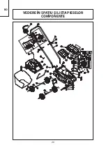
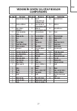
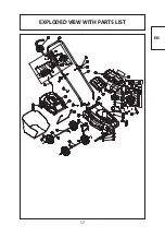
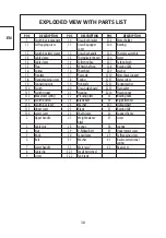
Page 27: ...26 RO VEDERE N SPA IU I LISTA PIESELOR COMPONENTE...

