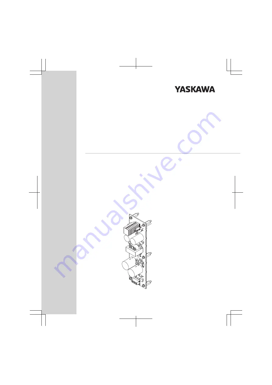
YASKAWA U1000 Series Installation Manual Download Page 1

24 V

制御電源ユニット

安川 

U1000

シリーズオプション

取扱説明書

形式:

PS-U10L, PS-U10H

24 V Power Supply

YASKAWA U1000-Series Option

Installation Manual

Type: PS-U10L, PS-U10H

To properly use the product, read this manual thoroughly and retain 
for easy reference, inspection, and maintenance. Ensure the end user 
receives this manual.

製品を安全にお使いいただくために,本書を必ずお読みください。
また,本書をお手元に保管していただくとともに,最終的に本製品をご使用になる
ユーザー様のお手元に確実に届けられるよう,お取り計らい願います。

COSMOS(140×182)(和英併記)新CI

MANUAL NO.  TOBP C730600 95A

Summary of Contents for U1000 Series

Page 1: ...00 Series Option Installation Manual Type PS U10L PS U10H To properly use the product read this manual thoroughly and retain for easy reference inspection and maintenance Ensure the end user receives...

Page 2: ...en permission of Yaskawa No patent liability is assumed with respect to the use of the information contained herein Moreover because Yaskawa is constantly striving to improve its high quality products...

Page 3: ...ation Manual 3 Table of Contents 1 PREFACE AND SAFETY 4 2 PRODUCT OVERVIEW 9 3 RECEIVING 10 4 OPTION COMPONENTS 11 5 INSTALLATION PROCEDURE 13 6 VERIFYING OPERATION 41 7 SPECIFICATIONS 42 8 STANDARDS...

Page 4: ...porate a product manufactured by Yaskawa must be supplied to the end user with appropriate warnings and instructions as to the safe use and operation of that part Any warnings provided by Yaskawa must...

Page 5: ...nverter YASKAWA U1000 Series Technical Manual Low Harmonics Regenerative Matrix Converter for Elevator Applications YASKAWA U1000L Series Quick Start Guide Low Harmonics Regenerative Matrix Converter...

Page 6: ...ure to obey these safety messages in the manual can cause serious injury or death Yaskawa is not responsible for injuries or damage to equipment caused by ignoring the safety messages DANGER Indicates...

Page 7: ...tive or the nearest Yaskawa sales office and give the manual number shown on the front cover DANGER Obey the safety messages in this manual Failure to obey will cause death or serious injury The opera...

Page 8: ...00 95A U1000 Series Option PS U10 Installation Manual Option Label Warnings Warning information is displayed on the package Follow all warnings and safety instructions when using the product Figure 1...

Page 9: ...parameter data Note Parameter settings cannot usually be changed without drive main circuit power regardless of whether the control circuit has enough power to operate However parameter settings can b...

Page 10: ...f the option does not operate correctly Option Package Contents Tools Required to Install the Option A Phillips screwdriver M4 metric 1 2 U S standard size to install the option A straight edge screwd...

Page 11: ...Manual 11 4 Option Components 4 Option Components Option Figure 2 Figure 2 24 V Power Supply Option Components Option Nameplate Figure 3 Figure 3 PS U10L Nameplate Example A Connector CN1 C Model cod...

Page 12: ...omponents 12 YASKAWA ELECTRIC TOBP C730600 95A U1000 Series Option PS U10 Installation Manual Terminal Block TB1 Terminal Functions Terminal Function 24 24 Vdc Input 0 0 V FE Ground TOBP_C730600_95A_2...

Page 13: ...rous voltages to make sure that the drive is safe Failure to obey will cause death or serious injury Disconnect the power to the drive and wait for the charge indicator LED to go off then remove the c...

Page 14: ...e while the drive is supplying voltage Incorrect equipment sequencing can cause damage to the drive Do not connect or operate damaged equipment or equipment with missing parts Failure to obey can caus...

Page 15: ...for the option Find your drive model number on the drive nameplate and use Table 2 to find the correct installation method Table 2 Model Specific Installation Methods Drive Model Installation Method P...

Page 16: ...ure 4 to Figure 11 show the locations where the option is to be installed Figure 4 Figure 4 U1000 Z1000U 2 0028 4 0011 to 4 0034 Figure 5 Figure 5 U1000 Z1000U 2 0042 to 2 0081 4 0040 to 4 0077 U1000L...

Page 17: ...U10 Installation Manual 17 Figure 6 Figure 6 U1000 Z1000U 2 0104 2 0130 4 0096 4 0124 U1000L 2 0081 2 0104 4 0077 4 0096 Figure 7 Figure 7 U1000 Z1000U 2 0154 2 0192 4 0156 4 0180 Installation positi...

Page 18: ...00 95A U1000 Series Option PS U10 Installation Manual Figure 8 Figure 8 U1000 Z1000U 2 0248 4 0216 4 0240 Figure 9 Figure 9 U1000 Z1000U 4 0302 to 4 0414 Installation position of the option Installati...

Page 19: ...tion Procedure YASKAWA ELECTRIC TOBP C730600 95A U1000 Series Option PS U10 Installation Manual 19 Figure 10 Figure 10 U1000 Z1000U 4 0477 4 0590 Installation position of the option TOBP_C730600_95A_2...

Page 20: ...on Procedure 20 YASKAWA ELECTRIC TOBP C730600 95A U1000 Series Option PS U10 Installation Manual Figure 11 Figure 11 U1000 Z1000U 4 0720 to 4 0930 Installation position of the option TOBP_C730600_95A_...

Page 21: ...erminal Number Screw Size Tightening Torque N m in lb Bare Cable Crimp Terminals Wire Type Recomm Gauges mm2 Applicable Gauges mm2 Recomm Gauges mm2 Applicable Gauges mm2 24 0 FE M2 0 22 to 0 25 1 95...

Page 22: ...When all indicators are OFF remove the covers before measuring for dangerous voltages to make sure that the drive is safe Failure to obey will cause death or serious injury NOTICE Damage to Equipment...

Page 23: ...e 14 Figure 14 Connect the Option 3 Pull the loose end of the connection cable out of the drive and connect to CN1 on the option NOTICE Put the cable connector in the correct position to connect it to...

Page 24: ...d terminal cover G and replace the digital operator F Figure 16 Figure 16 Replace the Front Cover Terminal Cover and Digital Operator Note Wire the option to easily fit the front covers back onto the...

Page 25: ...When all indicators are OFF remove the covers before measuring for dangerous voltages to make sure that the drive is safe Failure to obey will cause death or serious injury NOTICE Damage to Equipment...

Page 26: ...e 18 Figure 18 Connect the Option 3 Pull the loose end of the connection cable out of the drive and connect to CN1 on the option NOTICE Put the cable connector in the correct position to connect it to...

Page 27: ...d terminal cover G and replace the digital operator F Figure 20 Figure 20 Replace the Front Cover Terminal Cover and Digital Operator Note Wire the option to easily fit the front covers back onto the...

Page 28: ...When all indicators are OFF remove the covers before measuring for dangerous voltages to make sure that the drive is safe Failure to obey will cause death or serious injury NOTICE Damage to Equipment...

Page 29: ...ure 22 Connect the Option 3 Connect one end of the included connection cable A to CN1 on the option Connect the other end to CN19 on the drive NOTICE Put the cable connector in the correct position to...

Page 30: ...E and terminal cover G and replace the digital operator F 1 Figure 24 Replace the Front Cover Terminal Cover and Digital Operator Note Wire the option to easily fit the front covers back onto the driv...

Page 31: ...hen all indicators are OFF remove the covers before measuring for dangerous voltages to make sure that the drive is safe Failure to obey will cause death or serious injury NOTICE Damage to Equipment O...

Page 32: ...tion Connect the other end to CN19 on the drive NOTICE Put the cable connector in the correct position to connect it to the drive and option An incorrect connection can cause damage to the connector a...

Page 33: ...E and terminal cover G and replace the digital operator F 1 Figure 28 Replace the Front Covers Terminal Cover and Digital Operator Note Wire the option to easily fit the front covers back onto the dri...

Page 34: ...hen all indicators are OFF remove the covers before measuring for dangerous voltages to make sure that the drive is safe Failure to obey will cause death or serious injury NOTICE Damage to Equipment O...

Page 35: ...d to CN19 on the drive NOTICE Put the cable connector in the correct position to connect it to the drive and option An incorrect connection can cause damage to the connector and the drive Figure 29 Fi...

Page 36: ...E and terminal cover G and replace the digital operator F 1 Figure 32 Replace the Front Covers Terminal Cover and Digital Operator Note Wire the option to easily fit the front covers back onto the dri...

Page 37: ...hen all indicators are OFF remove the covers before measuring for dangerous voltages to make sure that the drive is safe Failure to obey will cause death or serious injury NOTICE Damage to Equipment O...

Page 38: ...ion cable B to CN1 on the option Connect the other end to CN19 on the drive NOTICE Put the cable connector in the correct position to connect it to the drive and option An incorrect connection can cau...

Page 39: ...E and terminal cover G and replace the digital operator F 1 Figure 36 Replace the Front Covers Terminal Cover and Digital Operator Note Wire the option to easily fit the front covers back onto the dri...

Page 40: ...o not pinch wire insulation in the terminals and cut frayed wires NOTICE Correctly connect an external 24 V power source to the option terminal block Refer to Option Specifications on page 42 for info...

Page 41: ...operating correctly 4 The digital operator on the drive will flash Fdv or AUv for approximately 10 seconds to show an undervoltage condition on the drive If Fdv or AUv does not flash on the display sc...

Page 42: ...he drive environmental specifications Specifications Input Operating Voltage 24 Vdc 20 19 2 V to 28 8 V Input Current 1 9 A Consumption Power 38 W Output Ride Thru time when power is off Over 50 ms Am...

Page 43: ...e decreases below 50 Vdc When all indicators are OFF remove the covers before measuring for dangerous voltages to make sure that the drive is safe Failure to obey will cause death or serious injury WA...

Page 44: ...pecified on the drive before touching any components Only let authorized persons install wire maintain examine replace parts and repair the drive and option Failure to obey can cause death or serious...

Page 45: ...ials to mount the drive harmonic filter module or option Failure to obey could cause death or serious injury by fire Attach the drive harmonic filter module and option to metal or other noncombustible...

Page 46: ...use damage to the drive After blowing a fuse or tripping an Earth Leakage Circuit Breaker ELCB wait at least 5 minutes and make sure that the CHARGE lamp is off before starting the drive again or oper...

Page 47: ...ndards Compliance This product is evaluated in accordance with UL standard UL508C and complies with UL requirements Installation Area Do not install the product in a pollution degree 3 or 4 area UL st...

Page 48: ...cts used with this product comply with all applicable European directives and other national regulations if required CE Low Voltage Directive Compliance Yaskawa tested this product according to Europe...

Page 49: ...on Method Install the option with the following conditions to make sure that other devices and machinery used with this option also comply with EMC guidelines 1 Use dedicated shield cable for the opti...

Page 50: ...repair the defective product and provide shipping to and from the site free of charge However if the Yaskawa Authorized Service Center determines that the problem with the product is not due to defec...

Page 51: ...ed or manufactured for use in devices or systems that may directly affect or threaten human lives or health Customers who intend to use the product described in this manual for devices or systems rela...

Page 52: ...the bottom of the back cover Date of Publication Revision Number Web Revision Number Section Revised Content February 2023 2 0 Back cover Revision Address May 2019 1 0 Back cover Revision Address Nove...

Page 53: ...h YASKAWA ELECTRIC CHINA CO LTD 22F Link Square 1 No 222 Hubin Road Shanghai 200021 China Phone 86 21 5385 2200 Fax 86 21 5385 3299 www yaskawa com cn YASKAWA ELECTRIC CHINA CO LTD BEIJING OFFICE Room...

Reviews: