Installation and Operation Guide SOLECTRIA XGI 1500 (Rev E, 5 Mar. 2021)
20 of 70
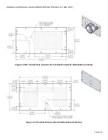
Figure 3-12 Prohibited Transformer Configurations
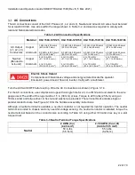
Equipment Grounding
The XGI 1500 must be bonded using equipment grounding provisions. Do not attempt to ground either DC
pole. The XGI 1500 includes provisions for terminating equipment grounding conductors and other conductors
used for bonding. One M8 stud with an M8 external-tooth star nut is located inside the inverter wiring section (
Figure 3-13). Use a 13mm socket and torque to 90 in-lbs (12.2 N-m). On the exterior of the inverter is an M6
threaded insert (
Figure 3-13) Torque this customer supplied fastener to 39 in-lbs (4.4N-m)
Figure 3-13 Ground Connection Inside and Outside Inverter
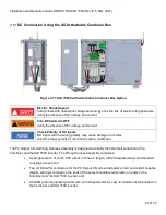
Table 3-1 Grounding and Bonding Connection Specifications
Improper Transformer Configuration
Inverter will not run and may have hazardous current. Connect transformer in specified
configurations only. Incorrect transformer configuration may cause damage to the inverter.
Material
XGI 1500-125/125
XGI 1500-125/150
XGI 1500-150/166
XGI 1500-166/166
Grounding
Conductor
Copper
Aluminum
4 to 1/0 AWG
(21.1 to 53.5 mm
2
)
4 to 1/0 AWG
(21.1 to 53.5 mm
2
)
4 to 1/0 AWG
(21.1 to 53.5 mm
2
)
4 to 1/0 AWG
(21.1 to 53.5 mm
2
)
M8 Stud
and Nut
M6 Threaded Insert


