4.2 Setup Procedure
4.2.5 Servo Commands to Use
4
Rotational Coor
dinate
S
y
s
tem
4-7
4.2.5
Servo Commands to Use
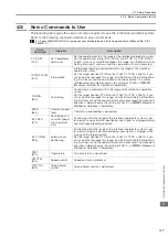
The following table gives the servo command required to use the rotational coordinate system.
Refer to the following manual for details on servo commands.
Σ
-7-Series MECHATROLINK-III Communications Standard Servo Profile Command Manual (Manual No.: SIEP
S800001 31)
Servo
Command
Operation
Description
POS_SET
(20h)
Set Coordinates
command
Set the coordinate within the range of the rotational coordinate system.
Set the coordinate setting (POS_DATA) so that Pn87C
≤
POS_DATA
≤
Pn87A. If you set a value that exceeds this range, an A.94B alarm (Data
Setting Warning 2) will occur and the command will not be executed.
INTERPOLATE
(34h)
Interpolation
Interpolation feeding is performed within the range of the rotational
coordinate system.
Set the target position (TPOS) so that Pn87C
≤
TPOS
≤
Pn87A. If you
set a value that exceeds this range, an A.94B alarm (Data Setting Warn-
ing 2) will occur and the command will not be executed. The motor
rotation direction is determined by the setting of Pn87E = n.
X
(Movement Method for Rotational Coordinates).
POSING
(35h)
Positioning
Positioning is performed within the range of the rotational coordinate
system.
Set the target position (TPOS) so that Pn87C
≤
TPOS
≤
Pn87A. If you
set a value that exceeds this range, an A.94B alarm (Data Setting Warn-
ing 2) will occur and the command will not be executed. The movement
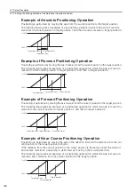
direction is determined by the setting of Pn87E = n.
X (Movement
Method for Rotational Coordinates).
FEED
(36h)
Constant-speed
feed
Constant-speed feeding is performed.
EX_FEED
(37h)
Positioning at a
constant speed
for an external
input
Positioning within the range of the rotational coordinate system is per-
formed by using an external positioning input signal as a trigger during a
constant-speed feeding operation.
EX_POSING
(39h)
External input
positioning
Positioning within the range of the rotational coordinate system is per-
formed by using an external positioning input signal as a trigger while
moving to the target position.
Set the target position (TPOS) so that Pn87C
≤
TPOS
≤
Pn87A. If you
set a value that exceeds this range, an A.94B alarm (Data Setting Warn-
ing 2) will occur and the command will not be executed. The movement
direction is determined by the setting of Pn87E = n.
X (Movement
Method for Rotational Coordinates).
ZRET
(3Ah)
Origin return
An origin return is performed.
VELCTRL
(3Ch)
Speed control
Speed control is performed.
TRQCTRL
(3Dh)
Torque (force)
control
Torque (force) control is performed.


