3.5 Wiring the Power Supply to the SERVOPACK
3.5.2 Wiring Procedure for Main Circuit Connector
3
Wiring and Connection
s
3-27
You can use a single-phase, 200-VAC power supply input with the following models.
•
SGD7C-1R6A, -2R8A, and -5R5A
If you use a single-phase, 200-VAC power supply input for the SERVOPACK’s main circuit
power supply, set parameter Pn00B to n.
1
(Use a three-phase power supply input as a
single-phase power supply input). Refer to the following section for details.
5.3.2 Single-phase AC Power Supply Input/Three-phase AC Power Supply Input Setting
•
DC Power Supply Input
If you use a DC power supply input to the SERVOPACK, set Pn001 to n.
1
(Input DC
power) before inputting the power supply. Refer to the following section for details.
5.3.1 AC Power Supply Input/DC Power Supply Input Setting
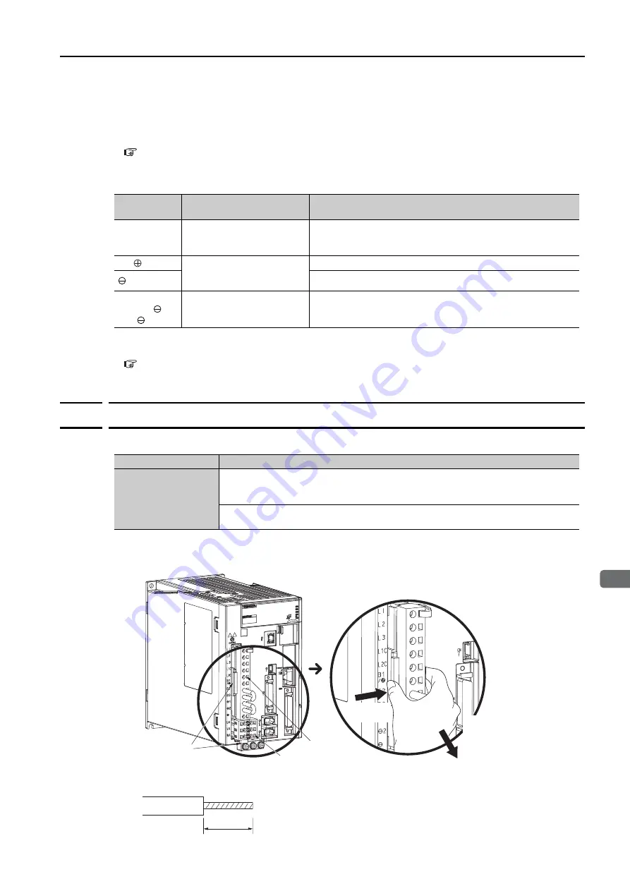
3.5.2
Wiring Procedure for Main Circuit Connector
•
Required Items
1.
Remove the main circuit connector and motor connector from the SERVOPACK.
2.
Remove the sheath from the wire to connect.
Terminal
Symbols
Terminal Name
Specifications and Reference
L1C and L2C
Control power supply termi-
nals
L1C: 270 VDC to 324 VDC, -15% to +10%, L2C: 0 VDC
Or
L2C: 270 VDC to 324 VDC, -15% to +10%, L1C: 0 VDC
B1/
Main circuit power supply
input terminals for DC
power supply input
270 VDC to 324 VDC, -15% to +10%
2
0 VDC
L1, L2, L3,
B2, B3, 1,
and
–
None. (Do not connect anything to this terminal.)
Required Items
Remarks
Spring Opener or Flat-
blade Screwdriver
•
Spring Opener
SERVOPACK accessory
(You can also use model 1981045-1 from Tyco Electronics Japan G.K.)
•
Flat-blade screwdriver
Commercially available screwdriver with tip width of 3.0 mm to 3.5 mm
Lock
s
1. Pre
ss
in
on the lock.
2. Pre
ss
in on the lock
s
to
remove the connector
s
.
Enlarged View
Main circuit
connector
S
ervomotor connector
8 mm to 9 mm


