


8
Electrical Equipment Specification
8.1 Position of Limit Switch
8-1
175873-1CD
HW1483557
VS100
8
Electrical Equipment Specification
8.1
Position of Limit Switch
8.1.1 Specification of Limit Switch
1. The interference limit switch at S-, L-, E- and U-axes electrically limit
the operating range of respective axes by adjusting the position of the
dog using the limit switch.
The positions of the mechanical limits (mechanical stoppers) at S-axis
are changeable.
When the limit switch is activated, the power supply to the manipulator
is interrupted, then the manipulator makes an emergency stop as a
result. Refer to
section 8.9 “Overrun/Tool Shock Sensor Releasing”
in
“DX200 INSTRUCTIONS”
for releasing the status of this overrun.
2. The range of S-, L-, E- and U-axes limit switches are set to the
maximum operating range before shipping.
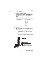
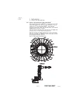
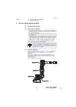
8.1.2 Position of Limit Switch
The limit switches are optional. For the S-, L-, E- and U-Axes with limit
switches specifications, L.S. are located on S-, L-, E-, and U-Axis
respectively.
For the location, refer to
Fig. 8-1 “Location of Limit Switches”
. The
inspection and adjustment of the limit switches should be made after
removing the cover.
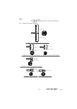
Fig. 8-1: Location of Limit Switches
NOTE
In case of re-adjusting the operating range of each subject
axis, it is also required to change the dog location and limit
values in software. Contact your YASKAWA representative
if re-adjustment is required.
L-axis overrun
limit switch
S-axis overrun
limit switch
U-axis interference
limit switch
E-axis overrun
limit switch
48 of 91


