


6
Disassembly and Reassembly of the Speed Reducer
6.1
Disassembly and Reassembly of the S-Axis Speed Reducer
6-2
HW1484673
HW1484673
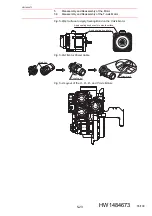
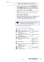
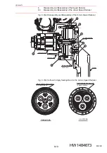
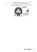
6. Tighten the hexagon socket head cap screws
and
with the
tightening torque shown in
. If the S-axis mechanical
stoppers
,
, and
were removed during disassembly, mount
them and tighten them with the tightening torque shown in
7. Reassemble and mount the S-axis motor
.
(Refer to
chapter 5.1 “Disassembly and Reassembly of the S-Axis
(When replacing the speed reducer, replace the input gear, too.)
8. Mount the internal wiring harness.
(Refer to
.)
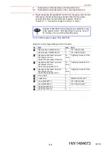
9. Replenish grease (Molywhite RE No.00) from the grease inlet. Mount
the hexagon socket head plugs at grease inlets and the grease
exhaust ports after the replenishment of grease. (Refer to
chapter 4.1.2 “Grease Exchange Procedure”
(S-axis).)
10. Turn ON the power supply of the YRC1000.
NOTE
If grease is filled before the sealing bond is solidified, it may
cause grease to leak. After tightening the screws, leave it
30 minutes or more, and then fill with grease.
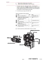
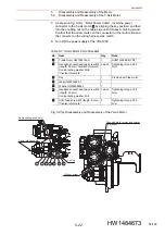
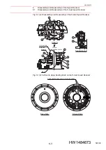
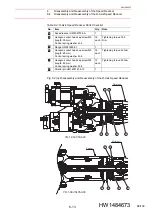
Table 6-1: S-Axis Speed Reducer Parts Checklist
No.
Item
Qty.
Note
Speed reducer HW1382898-A
1
Hexagon socket head cap screw M12
(length: 45 mm)
Conical spring washer 2H-12
16
each
Tightening torque 142
N•m
Hexagon socket head cap screw M12
(length: 35 mm)
Conical spring washer 2H-12
2
each
Tightening torque 142
N•m
Parallel pin HW1405948-10-25
1
Hexagon socket head cap screw M20
(length: 40 mm)
1
S-axis mechanical
stopper
Tightening torque 167
N•m
Collar HW9405875-1
1
S-axis mechanical
stopper
Hexagon socket head cap screw M12
(length: 55 mm)
Conical spring washer 2H-12
12
each
Tightening torque 142
N•m
Union KQ2L10-01AS
1
S-axis motor
1
SGM7G-30APK-YR1*
Input gear HW0313741-1
1
2
3
5
6
7
9
1
2
3
4
5
6
7
8
9
11
10
57/109