6.2 Inspection
YASKAWA ELECTRIC
TOEP C710687 02B FSDrive-MV1000 Instructions
193
Pe
ri
od
ic
In
spe
ct
io
n
&
Main
tenan
ce
6
u
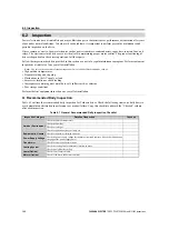
Recommended Periodic Inspection
outlines the recommended periodic inspections for Yaskawa drive installations. Although periodic inspections
should generally be performed once a year, the drive may require more frequent inspection in harsh environments or with
rigorous use. Periodic inspection will help to avoid premature deterioration in performance or product failure. Copy this
checklist and mark the “Checked” column after each inspection.
n
Periodic Inspection
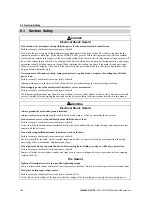
DANGER!
Electrical Shock Hazard. Do not connect or disconnect wiring or service equipment while the power is on. Failure to
comply will result in serious injury or death. Before servicing, disconnect all power to the equipment. There may be
multiple sources of power and control power may be present although the CHARGE indicator LED is extinguished.
Verify that control power is removed. The internal capacitor and the Power Cell exterior surface and interior remain
charged even after the medium-voltage power supply is turned off. Verify the CHARGE indicator LED is extinguished
before servicing and remove control power. To prevent electric shock, wait for at least the time specified on the warning
label after all indicators are OFF, and then measure for unsafe voltages to confirm the drive has reached a safe level
before servicing.
Table 6.2 Periodic Inspection Checklist
Inspection Area
Inspection Category
Details of Inspection
Page
Checked
Transformer Panel
Power Cell Panel
Entire transformer and
Power Cell panel
Megger check between the main circuit terminals and ground
terminal
Check for loose screws, bolts, or connectors.
Check for damage to parts or deformation or discoloration of
parts due to overheating or deterioration.
–
Check for soiling or adhesion of dust, etc.
–
Wires
Check for damage or deterioration of the cable sheath.
–
Transformer
Check the windings for damage, and check for breakage in the
insulation sheets.
Check the windings for accumulation of dust, and for
adhesion of foreign matter.
Power Cells
Check for leakage from the smoothing capacitor.
Confirm that the safety valve of the smoothing capacitor is not
protruding.
Confirm that the smoothing capacitor has not expanded.
Measure the capacitance of the smoothing capacitor.
(Check the indication on the gauge.)
Check for loose screws or bolts.
Check that the main circuit fuse and the control fuses on the
boards are normal.
Check for accumulated dust and dirt on the heatsink.
Surge absorber
Make sure the appearance is clean, the terminals are tightened
properly, and the installation bolts are securely fastened.
–
Control Panel
Circuits
Confirm no abnormalities in protective and indication circuits.
–
Relays
Confirm that there is no chattering noise during operation.
–
Confirm timer operation.
Check for damaged contacts.
Board
Check for abnormal smells and discoloration.
Confirm the power supply voltage.
Check for loose screws, bolts, or connections.
Digital Operator
Make sure data appears on the digital operator properly.
–
Check for soiling of the digital operator.
–
Cooling System
Air filter
Check for dirty or clogged filter.
Cooling fan
Check for abnormal vibration and noise.
Confirm the bearing operation.
Summary of Contents for FSDrive-MV1000 Series
Page 8: ...8 YASKAWA ELECTRIC TOEP C710687 02B FSDrive MV1000 Instructions...
Page 106: ...3 9 Wiring Check 106 YASKAWA ELECTRIC TOEP C710687 02B FSDrive MV1000 Instructions...
Page 210: ...6 7 Spare Parts 210 YASKAWA ELECTRIC TOEP C710687 02B FSDrive MV1000 Instructions...
Page 222: ...B 1 European Standards 222 YASKAWA ELECTRIC TOEP C710687 02B FSDrive MV1000 Instructions...


